Hello everyone hope you all doing great.
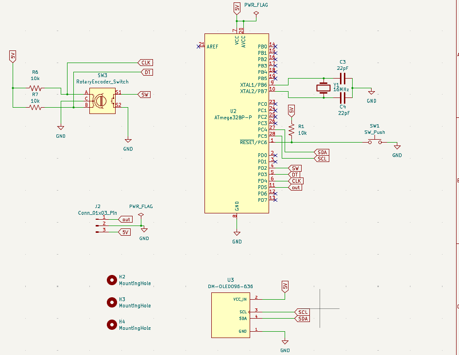
I am making a pcb that has rotary encoder and oled 128x64 pixels with bare atmega328p but it seems there is something wrong with the schematic design (oled still black after powerup but when connecting it to normal arduino uno dev board with same schematic it works). Below image shows the schematic. Thanks in advance.
No decoupling capacitance on the +5V rail or is it just now shown? The Uno schematic has 100nF close to the chip’s VCC and GND.
Are the loading capacitors for Y1 appropriately sized for the crystal and PCB? See https://blog.adafruit.com/2012/01/24/choosing-the-right-crystal-and-caps-for-your-design/. Also, the feedback resistor of 1MOhm (R2) is technically missing in your design.
Otherwise, there aren’t any crazy wrong things in the schematic.
Are you able to burn a simple test firmware that can output a simple LED blinky on a GPIO pin to verify that a firmware can run at all?
Did you burn the fuses of the ATMega328P correctly? See https://github.com/arduino/ArduinoCore-avr/blob/1.8.6/boards.txt#L95-L99.
1 Like
Thanks for the reply.
First of all, I am using already burned firmware on the atmega328p (using Arduino uno dev board)
I added 2 104 ceramic caps between 5V and GND but still oled not working.
I added 1 MOhm between crystal oscillator and nothing worked.
when I uploaded simple blink on gpio13 it worked.
I think that the SCL and SDA needs 10K ohm pullup to 5V
Then add some I²C pullups (usually 4.7K but whatever), add some initial sleep time in the firwmare in case the OLED is not ready yet, and run the I2C scanner sketch (https://playground.arduino.cc/Main/I2cScanner/). If you don’t have serial output, try re-encoding the number of found devices into a number of blinks.
1 Like
can i add 10KOhm or 3.3KOhm instead of 4.7KOhm
Edit: I tried both 10KOhm and 3.3KOhm still nothing on the oled also without any resistors the I2cScanner code turn led on after connecting the oled screen.
Code:
#include <Wire.h>

const int ledPin = 2; // LED connected to digital pin 2

void setup() {
Wire.begin();
pinMode(ledPin, OUTPUT);
digitalWrite(ledPin, LOW); // start with LED off
}

void loop() {
byte error, address;
bool deviceFound = false;

// Scan I2C bus
for (address = 1; address < 127; address++) {
Wire.beginTransmission(address);
error = Wire.endTransmission();


if (error == 0) {
  deviceFound = true;
  break; // stop scanning after finding first device
}


}

// Turn LED on or off
if (deviceFound) {
digitalWrite(ledPin, HIGH); // device found
} else {
digitalWrite(ledPin, LOW);  // no device found
}

delay(5000); // scan every 5 seconds
}
Do the I2C addresses match that are detected by the externally plugged in Uno and the on-board ATMega328P?
1 Like
Yes I think i should burn bootloader with the sketch in order to work
Edit: I found the solution. I burned the bootloader first then I uploaded the sketch and it works perfectly now!!