Hi, Last month my password word was stolen from my Arduino account and they have temporarily blocked me out so I thought to post my question here.
I’m working in Visual Studio Code with the Platform io extension on a Mega 2560.
I’m having trouble with the wire library.
When I run the following code I only see one byte of transmission on an oscilloscope over and over (every 100 ms). The clock rate is correct. I’ve tried everything I can think of including setting the clock rate but the second and third byte are no where to be seen. I’m working on a development board and my EE says that it looks like a software issue. All suggestions are welcome and most likely it’s something that I am forgetting although all the sample code I’ve viewed does not show me anything I am missing.
Thanks
RIck
#include <Wire.h>
void setup()
{
Wire.begin(); // join i2c bus (address optional for master)
}
thanks Norm for your reply. I am aware of the 7 bit address limits and so I believe the 0x37 I am sending is a valid address. It actually is a 6 bit address, while the following 0x7F is data. I think I can send a 0xFF as data as well. I am including arduino.h in my development code but not for this simple example.
Thanks
Thanks, I just needed to check. The I2C/TWI stuff uses 7 bit addresses (even if the address fits into 6!) and depending on a read or write action, shifts it up one bit and ORs in a 1 (for read) or a 0 (for write) to the lowest bit, bit 0, giving the two 8 bit addresses, one for reading and one for writing.
Time for another stupid question, or two:
Are you certain there’s a device on address 0x37? Have you scanned for one at that address? If you need a scanner, then the Arduino IDE has one in File->Examples->Wire->i2c_scanner. Failing that, I can send you one I wrote.
Does the device have its own inbuilt pull up resistors on the SCK and SDA lines? Those two lines must idle in a high state. Usually a 10K resistor, on each line to VCC is sufficient. However, the device’s data sheet will have details.
What is the I2C/TWI clock speed in use? While it might be correct for the device, some devices get uppity when used on a breadboard, due to stray capacitance caused by the breadboard. I have a 400 KHz device that only works up to 200 KHz on a breadboard.
What byte are you seeing on the oscilloscope? When you execute the endTransmission() function, that’s when the actual communications take place. The first thing that will happen is that the Mega 2560 will raise a start condition on the bus, then, when it gains control of the bus, it will transmit a SLAW address, the slave/peripheral write address which is ((0x37 << 1) | 0) or 0x6E. If this is what you are seeing, then I suspect that there is either no device at address 0x37; or the device at that address is not responding.
Normally, on receipt of its own SLAW address, a device will raise an ACK on the bus by pulling the SDA line low for one clock.
So:
Both SCL and SDA must idle high.
On a start condition, SCL stays high while SDA is pulled low.
Following the start, the Write address of the peripheral, SLAW, is written in the next 8 clocks. This will be 0x6E for your device with address 0x37.
If the SDA line is low on the next clock, then the device has responded and ACK’d it’s SLAW address. If the SDA line floats high for that one clock, then the device has not responded and the transmission is over.
Assuming the device ACK’d it’s SLAW, then the next byte on the bus will be 0x7F spread over the next 8 clocks, followed by the SDA line remaining/being pulled low to ACK the byte.
The next byte will be 0x55 on the next 8 clocks, then the SDA line should float high on the ninth clock to indicate a NACK, as this is the final byte.
If the device doesn’t respond to its SLAW address with an ACK, the controller will kill the transmission. Your loop is retrying the transmission every 100 milliseconds, so I suspect your problem is one or more of:
The device is not at address 0x37;
There’s no actual I2C/TWI device on the bus;
There is a device, but it’s dead!
The clock speed is way too high for the device even if it’s a correct speed for the device, but it’s on a breadboard.
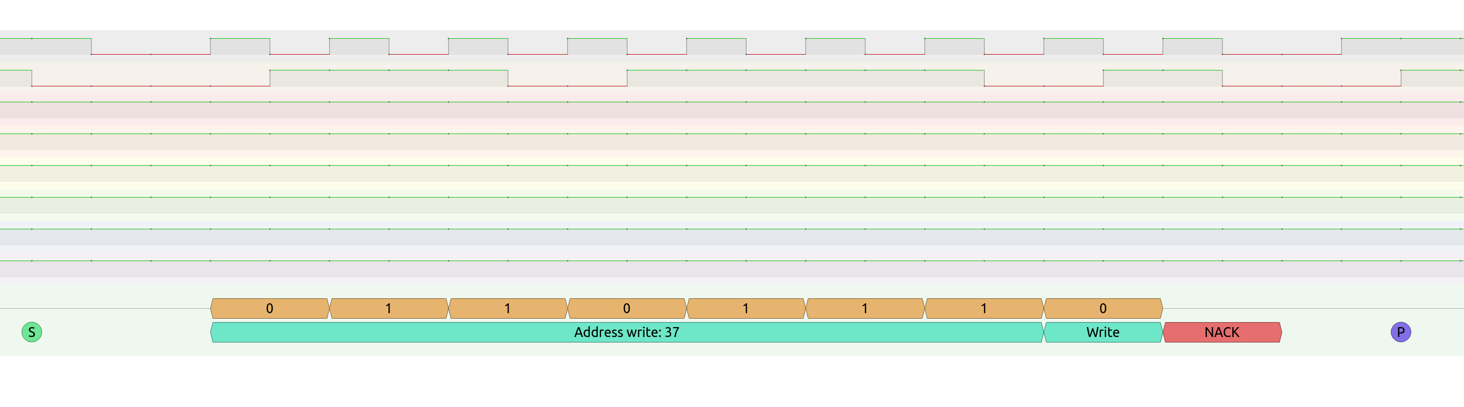
Further to the above, I copied your code exactly into an Uno, and ran it with nothing on the I2C/TWI bus except my logic analyser, this is what was repeated every 100 milliseconds:
You can see the start (S) followed by the 0x37 write address (shown here as 0x37 followed by a “write” bit of zero which equates to 0b01101110 or 0x6E, a NACK – because I have no device, and a stop (P).
Norm, this is excellent information you provided me. Thanks so much. I’ll have to try it out tomorrow when I get back to the lab.
I already checked the clock cycle and it’s correct at 100KHz.
The last time I wrote an i2c driver was in 2015 so thanks for refreshing my memory. I forgot or didn’t even know that if an i2c device was not hooked up that you would see only one byte like in your example.
That may explain my situation.
I’ll get back to you on Monday and give you my results.
Thanks so much for the information and you time.
Best Regards,
Rick
To be honest, you got me at a good time. I’ve just submitted the first draft of my second Arduino book for publication. I did quite a bit of work on I2C/TWI so it’s pretty fresh in my aging brain for a little while yet!
I’ve modified an interrupt driven I2C/TWI library just recently, for the book, which helped me with your problem. Working that out was “interesting”!
Hi Norm,
Well I started to write my own i2c scanner but then went back and read your email and noticed you recommended the Arduino scanner. I ran it and found that the address was wrong, just as you assumed.
So, I changed it and now see 3 bytes coming across the wire.
Thanks so much for your excellent advice and I appreciate your time. What’s the name of your book or do I search on Amazon for your name.
Hi Norm,
Somehow my replay below got appended to a previous post, so I am sending it again. Your overview of the i2c/twi was really helpful.
Well I started to write my own i2c scanner but then went back and read your email and noticed you recommended the Arduino scanner. I ran it and found that the address was wrong, just as you assumed.
So, I changed it and now see 3 bytes coming across the wire.
Thanks so much for your excellent advice and I appreciate your time. What’s the name of your book or do I search on Amazon for your name.
My first book is Arduino Software Internals, which explains how the hardware of the Arduino boards, specifically the Uno, talk to the software. Also, a fair bit about the Arduino compilation process, the language and so on. I discuss the new (back then) Arduino command line compiler and, obviously, PlatformIO. There’s a lot of technical info there. I don’t explain TWI in that book, but I do in my second. I think Amazon let’s you have a “look inside” if you want to take a quick look.
My second is Arduino Interrupts. That is not yet published, but I have an interview at the end of the month with Apress to discuss it.
I’m loathe to publish the URL to apress.com and Amazon.co.uk, as it’s been seen by some as spam, and as a moderator here, that’s not a good thing! If you search for me you’ll find me! .