Hello,
I’m using VS Code, Platformio and picoprobe (newest software) to debug my RPi Pico(W)… Uploading and debugging works (SMSIS-DAP) fine for me, but now my question:
How I can fetch my Serial-Output from the target pico, when connected over picoprobe?
I searched the web, but don’t find any working hint. Who can help me?
Best regards
Svens
P.S.: Excuse my bad English, but I’m from Germany
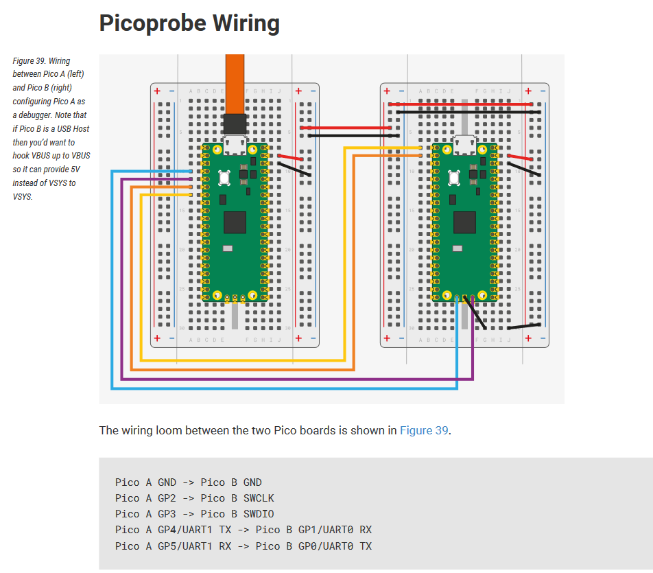
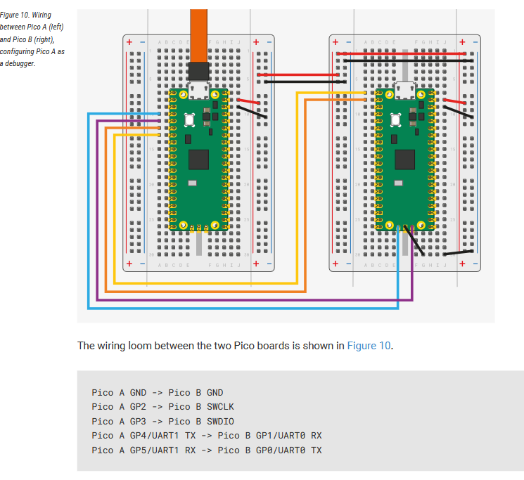
If you’ve loaded a Pico with the Picoprobe firmware, it automatically has a serial port, too. As the official documentation for the Picoprobe says, GP4 and GP5 of the Picoprobe should be connected to GP1 and GP0 of the target board.
The next point is to make the Arduino firmware actually output something on that serial (UART0, GP1/GP0).
For Arduino-Pico, you’ll have to explicitly use Serial1 in your code, which is the hardware UART. This is documented. It may also help to completely disable the USB serial port (and the Serial object) so that any code that uses Serial fails to compile and stands out, as is again documented.
For ArduinoCore-mbed, also use Serial1.
1 Like
Dear maxgerhardt,
many thanks for your quick answer to my question.
I’ve testet UART0 in the Arduino IDE 2.3.2 (with Serial.begin(115200), Serial1.println(“xxx”)) and I see the result on the terminal.
In VS code I use in platformio.ini following settings:
[env]
platform = https://github.com/maxgerhardt/platform-raspberrypi.git
framework = arduino
monitor_speed = 115200
board_build.core = earlephilhower
board_build.filesystem_size = 0.5m
lib_deps =
  adafruit/Adafruit SSD1306@^2.5.7
  adafruit/Adafruit GFX Library@^1.11.5
  majicdesigns/MD_AD9833@^1.2.2
  marlinfirmware/U8glib-HAL@^0.5.2

[env:pico]
board = pico
upload_protocol = cmsis-dap
debug_tool = cmsis-dap
build_type = debug
monitor_port = /dev/ttyUSB_picoprobe

[env:pico_debug]
board = pico
upload_protocol = cmsis-dap
debug_tool = cmsis-dap
debug_speed = 5000
build_type = debug
monitor_port = /dev/ttyUSB_picoprobe
In my main.cpp I also use:
Serial1.begin(115200);
Serial1.println(F(“TestText”));
But the “Test-Text” don’t appear on the opened Terminal.
Where is my mistake? Do I have to have special settings for the terminal and where I have to do this?
I hope, we can solve the problem. Any way upload and debugging is working very well.
Best regards from Germany
Svens
A serial monitor is not automatically started with the debug session.
Do you first of all see the regular print outputs when you upload + monitor the firmware that uses Serial1 regularly?
Thanks for your patience. But I’m very new with VS Code, PlatformIO & picoprobe.
I see in the opened terminal all prinouts when upload.
Do I’ve to change in my platformio.ini the entry “monitor_port”? My actual setting is “/dev/tinyUSB_picoprobe”. How can I after starting debugging open a termina/monitor listening on UART0/Serial1?
In the Arduino IDE 2.3.2 I can set the debug port to “Serial1” and all my Serial1.println-outputs can be seen on the opened terminal. I can’t find a way to listen on UART0 (Serial1) in VS Code/PlatformIO. Do you have a idea te make it work?
I don’t think PlatformIO can execute the “Monitor” task while doing the “Debug” tasks. I usually use a separate serial monitor program such as HTerm, PuTTY, etc.
Dear maxgerhardt,
many thanks again for your replay. I started a PuTTY-sesion and can now see the output on Serial1/UART0. So my problem is now solved and I can go on with my studies.
Have a nice weekend and best regards from Germany
Svens
Dear maxgerhardt,
here my update:
If I start first the debug(picoprobe) and later on a new terminal, this terminal show me the output of serial1.
Best reagrds
Svens
Dear Gerhart!
First I thank for your help. Now I am able to use picoprobe debugger. Sencond step how can I use a putty software to use serial port instead of COM5 virtual serial port required for terminal communication in my software to debug serial port reading from the keyboard and all dependencies.
Thanks
I’d recommend that when debugging with a Pico probe, to not run a USB stack on the RP2040, because halting the core might make it loose USB connection.
You can disable the USB stack per documentation.
You can use the hardware serial Serial1,usually on the GP0, GP1 pins, and connect them to the Picoprobe’s UART port as documented (chapter “debugprobe wiring”).
If you Serial1.begin(9600); then you should have no problems connecting with PuTTy at also 9600 baud. Just remember that the Debugprobe firmware will expect the serial monitor program to assert the DTR (virtual) line before it outputs any received data. I can also recommend hterm with respect to that.
Dear Gerhart!
First I thank for your help.
Now I start to understand using platformio. The project works fine I have sent to you.
Now I am able to use picoprobe debugger. Sencond step how can I use a putty software to use serial port instead of COM5 virtual serial port required for terminal communication in my software to debug serial port reading from the keyboard and all dependencies.
My hardware:
https://arduino-pico.readthedocs.io/en/latest/platformio.html#usb-stack
I’m repeating myself from my above post where I linked the exact chapter.
If you use this setup, where the left Pico runs the debugProbe firmware (aka, it’s the CMSIS-DAP debugger) and the right Pico runs your actual firmware, then you can use
Serial1.begin(115200);
Serial1.println("Hello");
to send output via GP0 of the right Pico, which will be picked up by GP5 of the left Pico (both must be set to 115200 baud of course), which then shows up in the COM port created by the left Pico (the debugProbe).
Of course, you can also use other pins for Serial TX / RX, as documented and documented.
Still not clear how to use the pin 6 (UART1 TX) and pin 7 (UART1 RX) of the debug pico to get an other serial port connected to the debugged pico. Need to use the debugged pico’s USB port as a terminal? Please help what is the exact setting for using this port instead of the serial monitor.
Thanks
The solution:
gpio_set_function(4, GPIO_FUNC_UART); // GPIO 4 → TX
gpio_set_function(5, GPIO_FUNC_UART); // GPIO 5 → RX
Serial1.begin(115200); // GPIO 4 (TX), GPIO 5 (RX)
Serial1.println(“Debug módban működik!”);
SET the apropriate pins for Serial1 function.
SOLVED!