On compiling and uploading blue pill code does not work within platformio as does in CubeIDE

I have STM32 blue pill, I make a simple LED blinking code within the CubeIDE, and it works fine
however, when I’ve tried to write the same code in Platformio, it doesn’t work at all while there is no error

following is the code and configuration

platformio.ini

[env:bluepill_f103c8]
platform = ststm32
board = bluepill_f103c8
framework = arduino

; change microcontroller
board_build.mcu = stm32f103c8t6

; change MCU frequency
board_build.f_cpu = 72000000L


upload_protocol = stlink

Arduino code

#include <Arduino.h>

#define ledPin PC13 //13
//LED_BUILTIN
void setup() {
  pinMode(ledPin,OUTPUT);
  Serial.begin(115200);
  Serial.println("startiing.....");
}

void loop() {
  digitalWrite(ledPin, HIGH);
   Serial.println("on");
  delay(1500);
  digitalWrite(ledPin, LOW);
  Serial.println("off");
  delay(1500);
}

compile message

Processing bluepill_f103c8 (platform: ststm32; board: bluepill_f103c8; framework: Arduino)
------------------------------------------------------------------------------------------------------------------------------------------------------------------------------------------------------------------Verbose mode can be enabled via `-v, --verbose` option
CONFIGURATION: https://docs.platformio.org/page/boards/ststm32/bluepill_f103c8.html
PLATFORM: ST STM32 (16.1.0) > BluePill F103C8
HARDWARE: STM32F103C8T6 72MHz, 20KB RAM, 64KB Flash
DEBUG: Current (stlink) External (blackmagic, cmsis-dap, jlink, stlink)
PACKAGES:
 - framework-arduinoststm32 @ 4.20500.230714 (2.5.0)
 - framework-cmsis @ 2.50700.210515 (5.7.0)
 - tool-dfuutil @ 1.11.0
 - tool-openocd @ 3.1200.0 (12.0)
 - tool-stm32duino @ 1.0.2
 - toolchain-gccarmnoneeabi @ 1.100301.220327 (10.3.1)
LDF: Library Dependency Finder -> https://bit.ly/configure-pio-ldf
LDF Modes: Finder ~ chain, Compatibility ~ soft
Found 12 compatible libraries
Scanning dependencies...
No dependencies
Building in release mode
Checking size .pio\build\bluepill_f103c8\firmware.elf
Advanced Memory Usage is available via "PlatformIO Home > Project Inspect"
RAM:   [          ]   4.1% (used 836 bytes from 20480 bytes)
Flash: [==        ]  18.9% (used 12396 bytes from 65536 bytes)
Configuring upload protocol...
AVAILABLE: blackmagic, cmsis-dap, dfu, jlink, mbed, stlink
CURRENT: upload_protocol = stlink
Uploading .pio\build\bluepill_f103c8\firmware.elf
xPack Open On-Chip Debugger 0.12.0-01004-g9ea7f3d64-dirty (2023-01-30-15:04)
Licensed under GNU GPL v2
For bug reports, read
        http://openocd.org/doc/doxygen/bugs.html
debug_level: 1

hla_swd
none separate

[stm32f1x.cpu] halted due to debug-request, current mode: Thread 
xPSR: 0x01000000 pc: 0x080005c0 msp: 0x20005000
** Programming Started **
Warn : Adding extra erase range, 0x08003190 .. 0x080033ff
** Programming Finished **
** Verify Started **
** Verified OK **
** Resetting Target **
shutdown command invoked
========================================================================================== [SUCCESS] Took 7.96 seconds ==========================================================================================
 *  Terminal will be reused by tasks, press any key to close it. 


That’s odd. Can you show the clock configuration page in STM32CubeMX with which your previous project worked?

clock configuration


void SystemClock_Config(void)
{
  RCC_OscInitTypeDef RCC_OscInitStruct = {0};
  RCC_ClkInitTypeDef RCC_ClkInitStruct = {0};

  /** Initializes the RCC Oscillators according to the specified parameters
  * in the RCC_OscInitTypeDef structure.
  */
  RCC_OscInitStruct.OscillatorType = RCC_OSCILLATORTYPE_HSE;
  RCC_OscInitStruct.HSEState = RCC_HSE_ON;
  RCC_OscInitStruct.HSEPredivValue = RCC_HSE_PREDIV_DIV1;
  RCC_OscInitStruct.HSIState = RCC_HSI_ON;
  RCC_OscInitStruct.PLL.PLLState = RCC_PLL_ON;
  RCC_OscInitStruct.PLL.PLLSource = RCC_PLLSOURCE_HSE;
  RCC_OscInitStruct.PLL.PLLMUL = RCC_PLL_MUL9;
  if (HAL_RCC_OscConfig(&RCC_OscInitStruct) != HAL_OK)
  {
    Error_Handler();
  }

  /** Initializes the CPU, AHB and APB buses clocks
  */
  RCC_ClkInitStruct.ClockType = RCC_CLOCKTYPE_HCLK|RCC_CLOCKTYPE_SYSCLK
                              |RCC_CLOCKTYPE_PCLK1|RCC_CLOCKTYPE_PCLK2;
  RCC_ClkInitStruct.SYSCLKSource = RCC_SYSCLKSOURCE_PLLCLK;
  RCC_ClkInitStruct.AHBCLKDivider = RCC_SYSCLK_DIV1;
  RCC_ClkInitStruct.APB1CLKDivider = RCC_HCLK_DIV2;
  RCC_ClkInitStruct.APB2CLKDivider = RCC_HCLK_DIV1;

  if (HAL_RCC_ClockConfig(&RCC_ClkInitStruct, FLASH_LATENCY_2) != HAL_OK)
  {
    Error_Handler();
  }
}

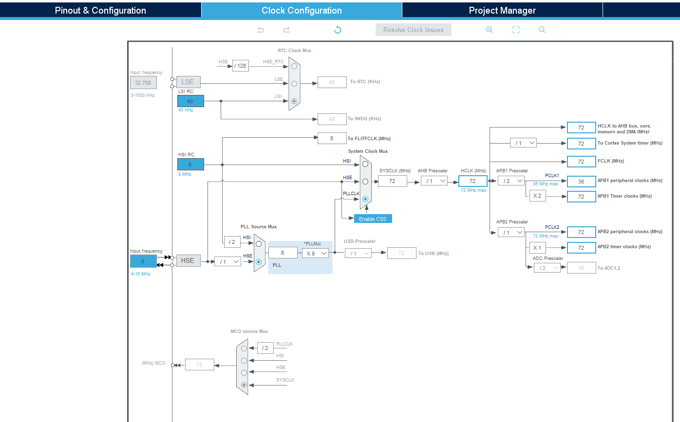
Okay, that matches the clock init code implicitly selected by board = bluepill_f103c8 (source), which is also HSE + PLL with factor 9 (source).

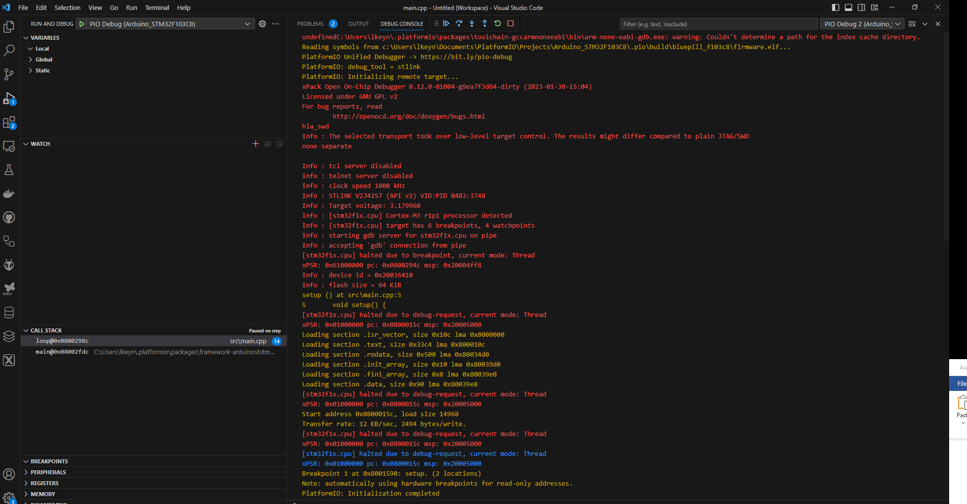
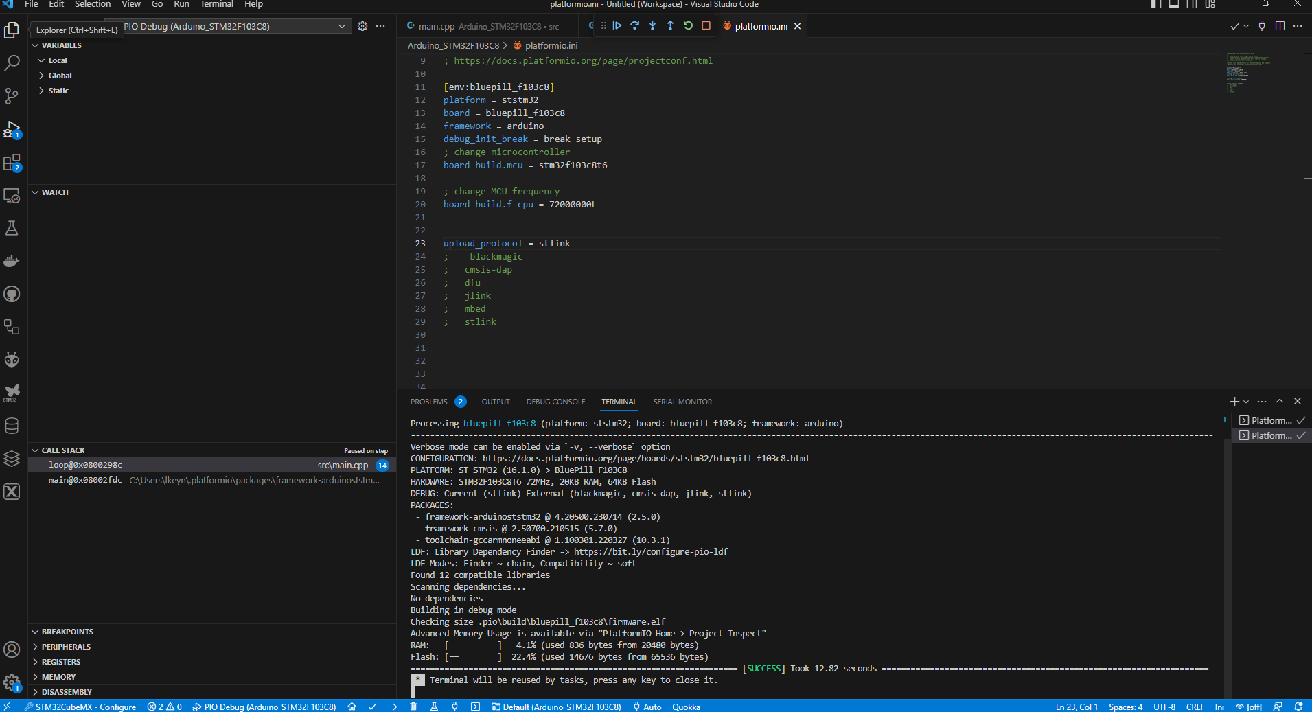
Since you upload via ST-Link, you should also be able to use debugging as normally. Add

debug_init_break = break setup

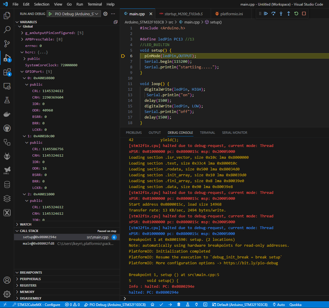
(docs) to the platformio.ini and save. Then, in the debugging sidepanel in VSCode, make sure the default “PIO Debug (project name)” is selected and press the play button.

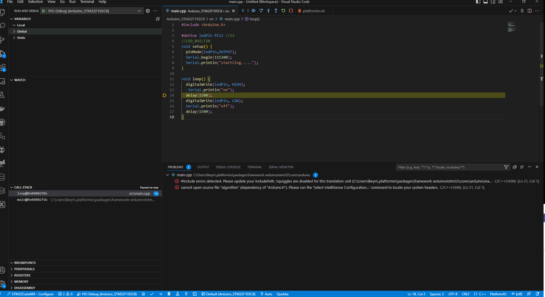
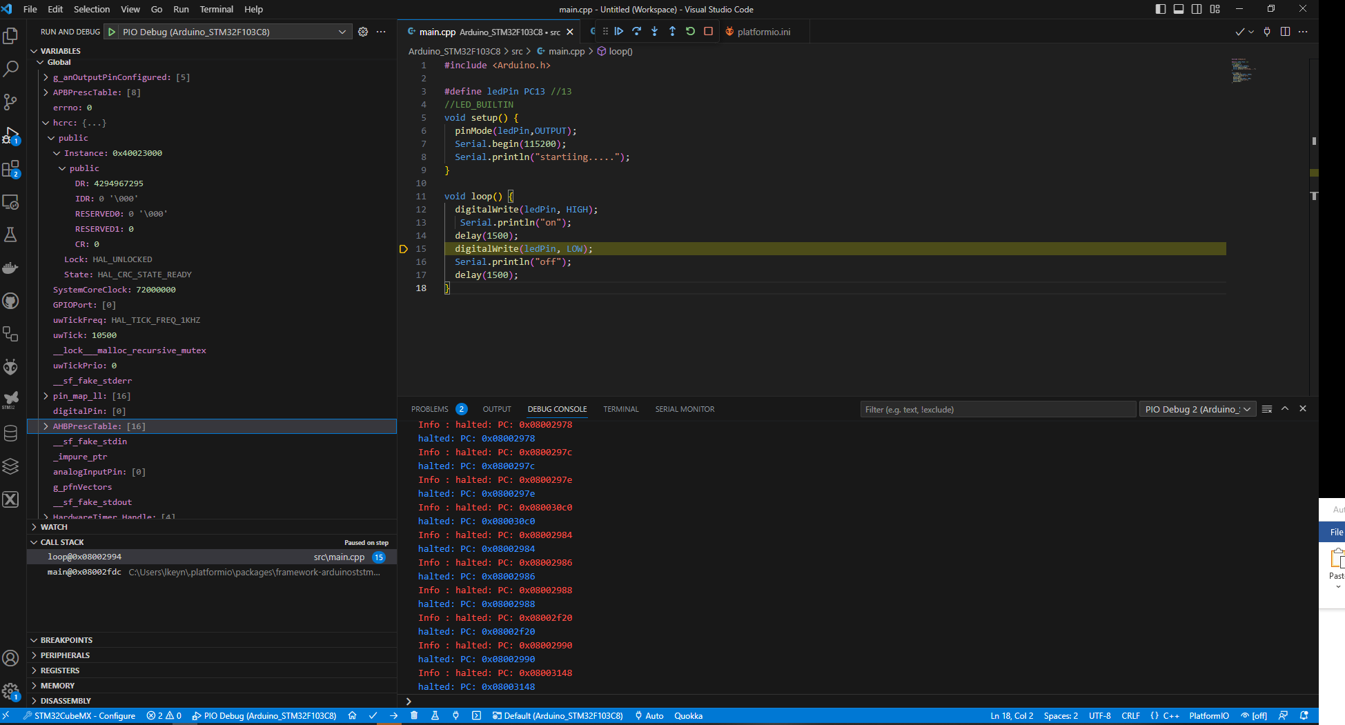
Does it break in your setup() function at all? If no, press the ‘Pause’ button. Where is it stuck? If yes, does it reach loop()? Does the LED state change after the digitalWrite()?

tnx @maxgerhardt
I add the command to ini file and press the debug button
it reaches the loop , but still no success

Okay, so firmware code is being executed. The pin definition of PC13 shuold also be totall okay. And you also set the GPIO mode as OUTPUT.

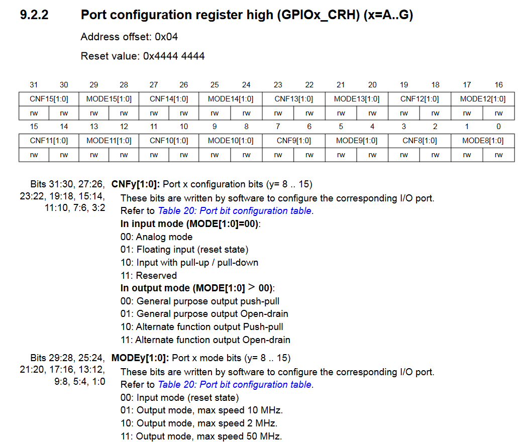
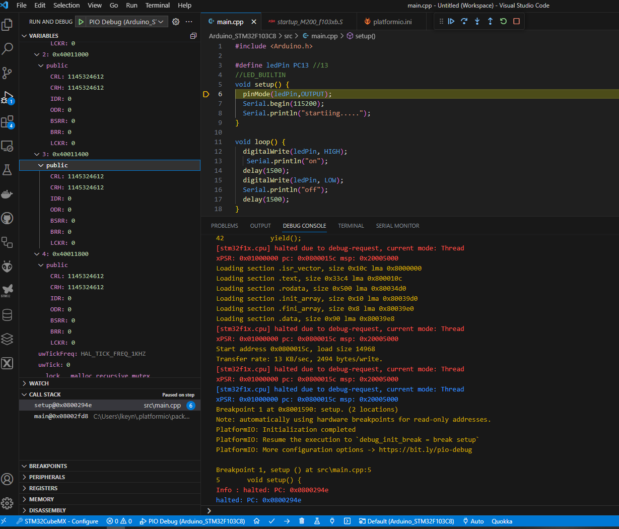
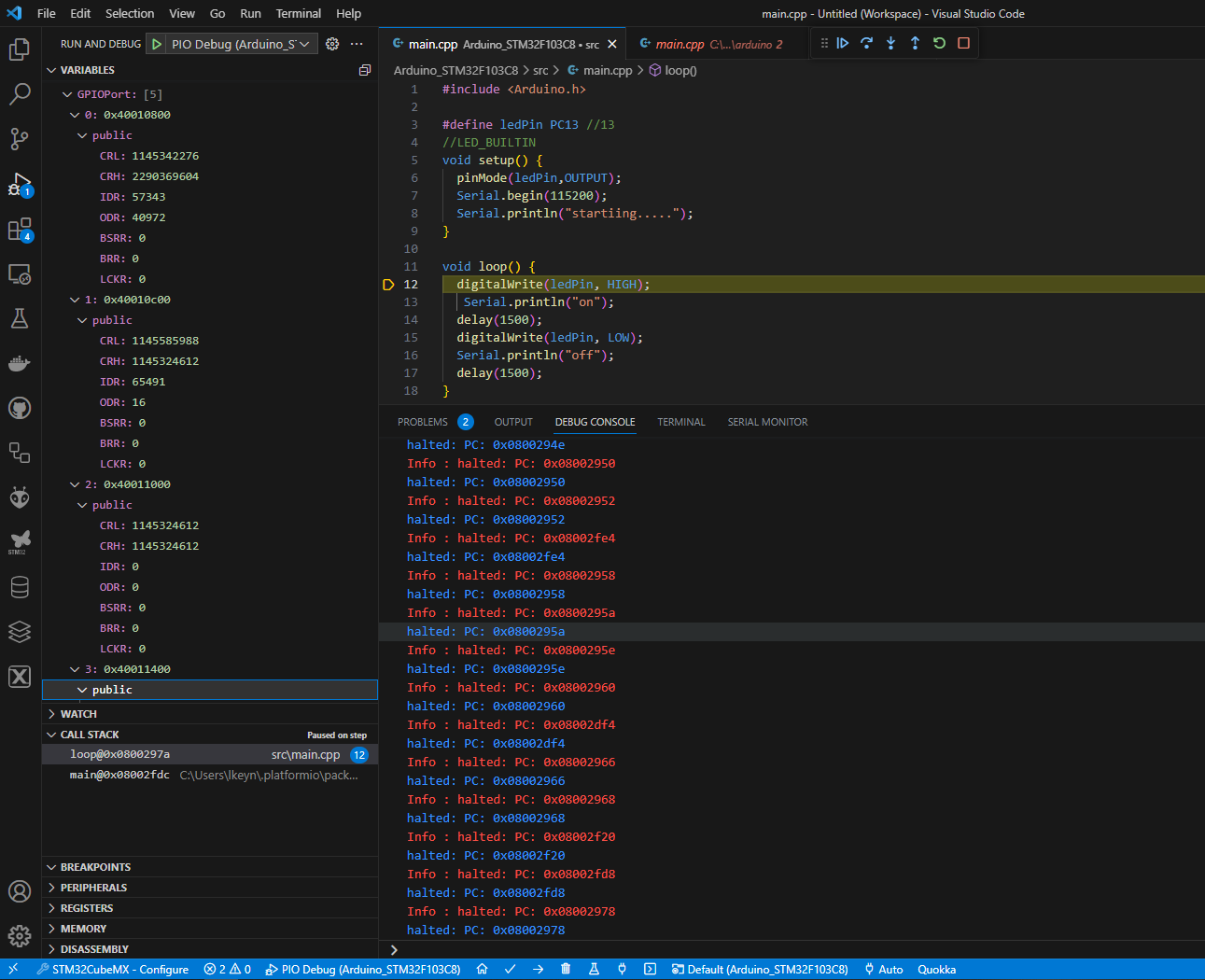
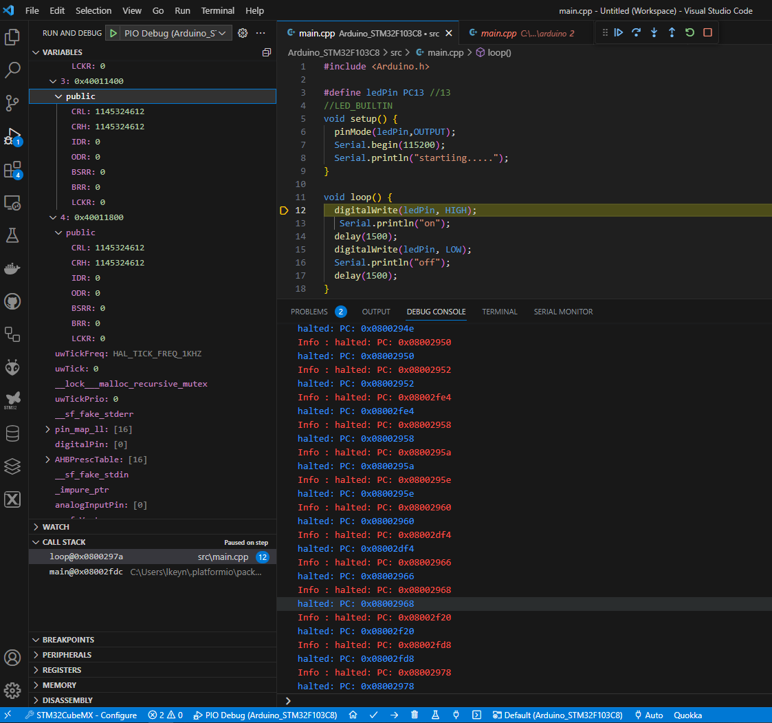
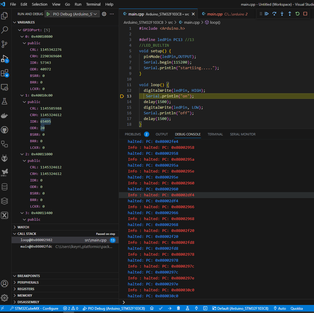
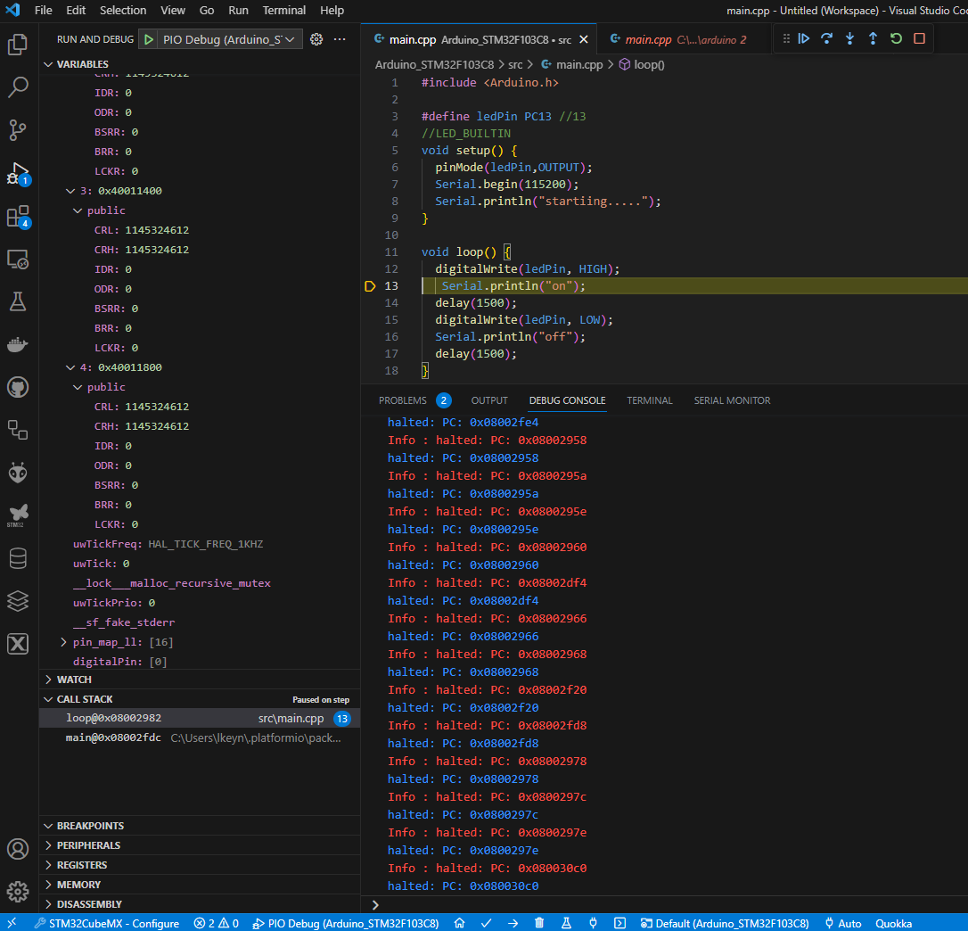
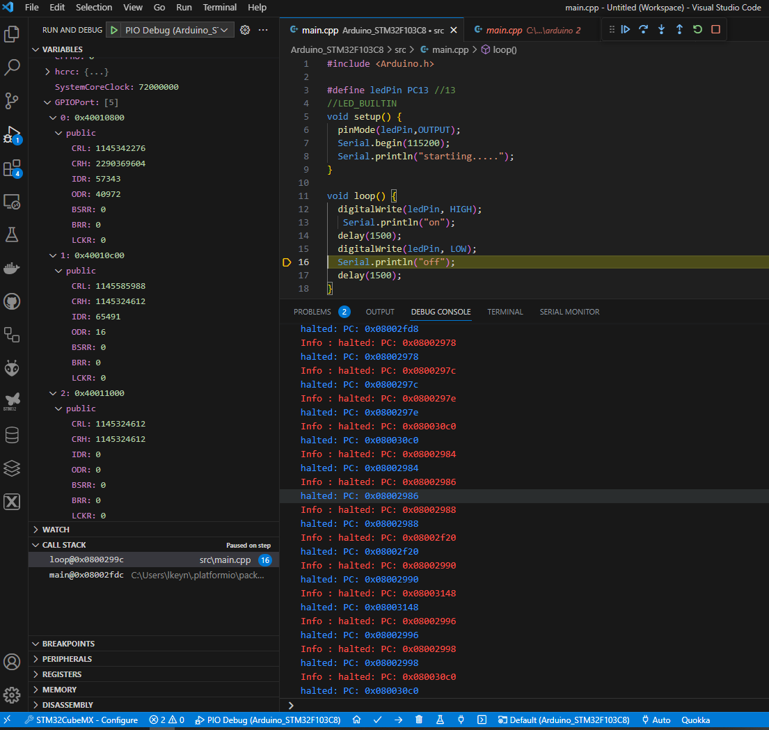
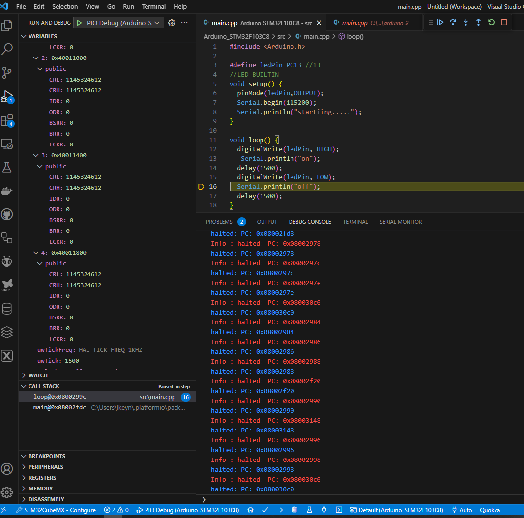
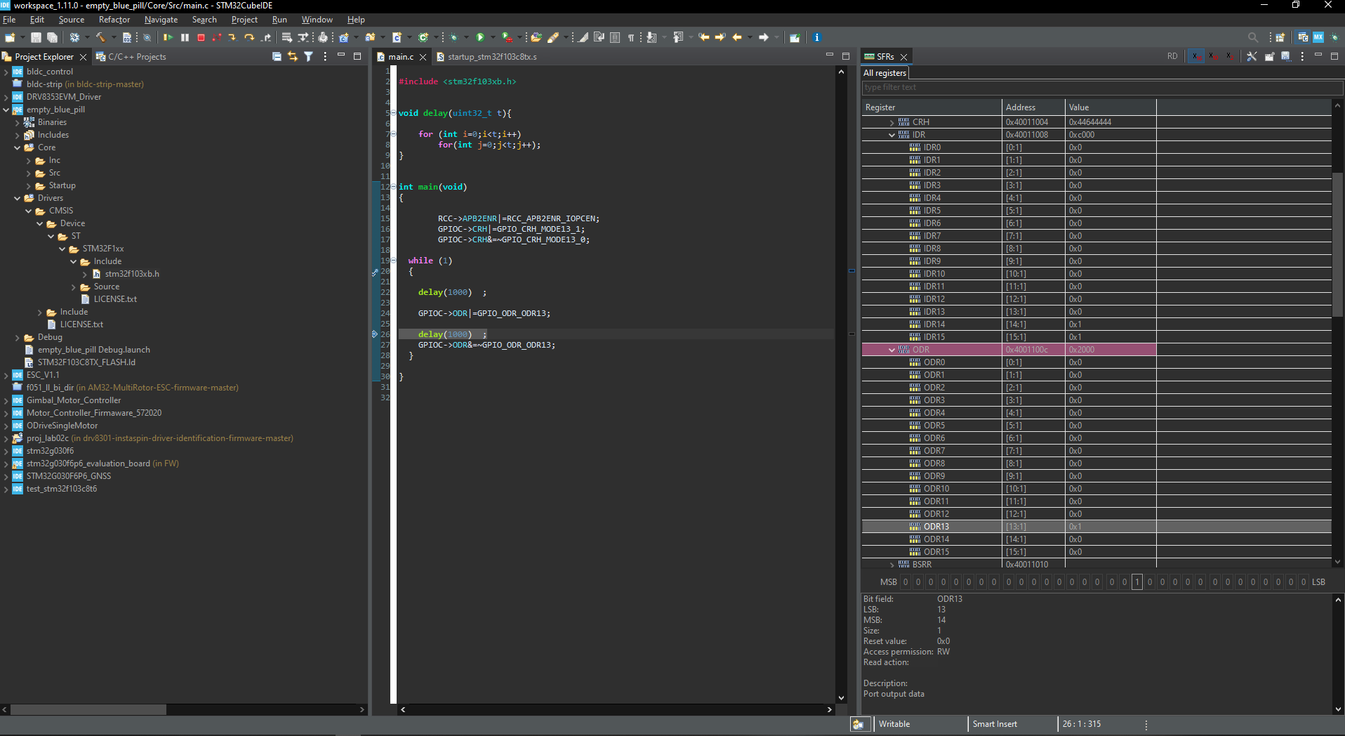
In the lower left corner of the debug session you have “Peripherals”. Can you take a screenshot of the GPIOC perpiheral with the CRH and ODR registers expanded, one screenshot for when the execution is at line 13 and when it’s at line 16?


tnx @maxgerhardt

@maxgerhardt , hi , any idea?

@maxgerhardt hi, Is any update really appreciated

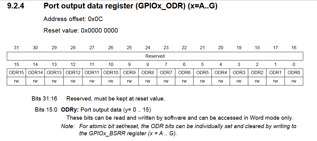
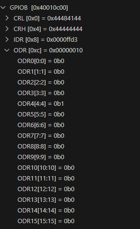
Sorry limited time right now, can you decode the aforementioned GPIOC registers and see if they match GPIO mode “output” and whether the ODR register shows a 1-bit after a digitalWrite(high) and 0-bit after a digitalWrite(low) at the 13th bit position from the right? (Counting the rightmost bit as index 0).

tnx @maxgerhardt , I debug the same program via cubeIDE and noticed the address are totally different
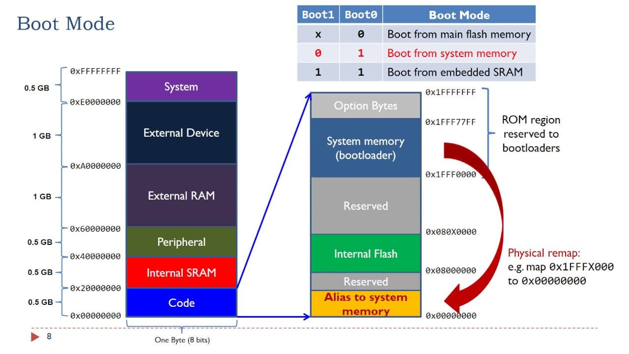
in Arduino address is 0x080030C0 (internal flash ) while according to the cudeIDE SRF tab, the address is 0x4001100C ( the last peripheral address is 0x40029054)

what configuration did I do wrong?
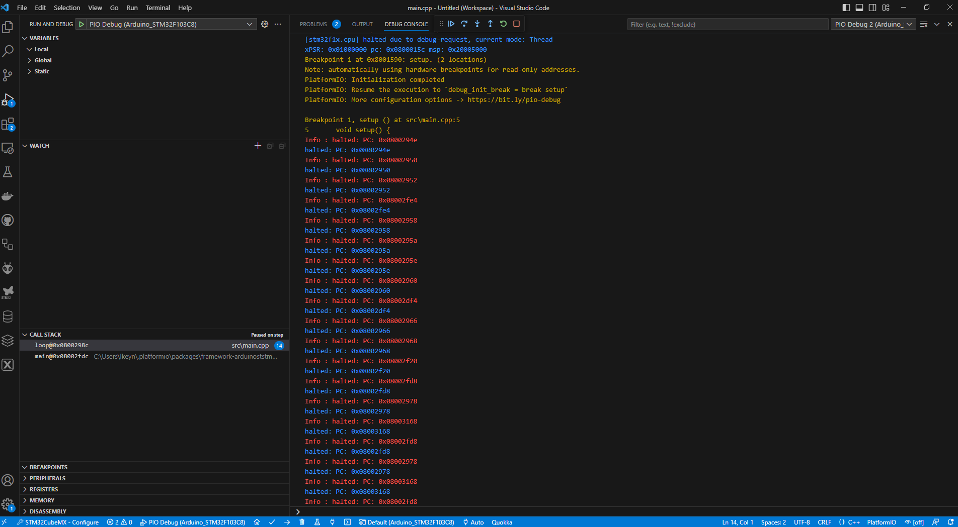
What’s the meaning of the red note in platformio? Info: halted PC : 0x000

@maxgerhardt , sorry to bother you again, but can you please look at my debugging images, platformio Arduino debugger shows it reads from the flash address (not surprised) while the cubeIDE precisely indicates the peripheral register address , so in that case memory address in platformio Arduino debugger is not helpful
any advice really appreciated

No, you’re looking at the variables view, you have to expand the “PERIPHERALS” further down.

tnx @maxgerhardt

find it
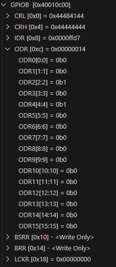
ODR2 from GPIOB has changed, whenever digitalWrite will be called
is there any way to export all peripheral registers to a text file and compare it on each step?

image

So you say doing a digitalWrite(PC13, HIGH); affects… PB2? This would be a major bug in the core if true.

The chip on the board 100% says “STM32F103C8T6”?