Nucleo F767ZI - Led LD4 RED

Hi,

I’m new to stm32 boards and I’m using it on platformIO with Arduino framework.
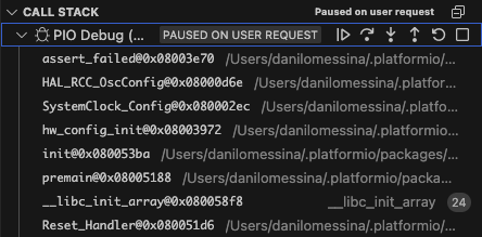
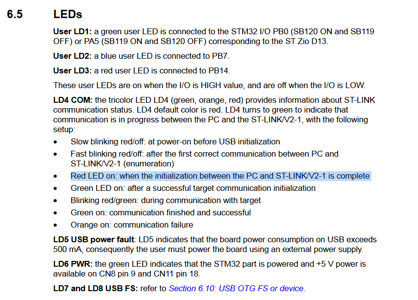
I have problems with the led LD4 (st-link led).

  • When I use the USB cable (JP3 jumper on U5V → powering the board using usb) the power led LD6 is green but the LD4 is red. When I upload the code the LD4 blinks red and then stable red again once flash is completed and nothing happens (in the code I turn on/off led LD1 and print something).

  • When I use external power (7.6V battery on VIN, JP3 jumper on VIN) the power led LD6 is green, the LD4 is green as well. Once I upload the code the LD4 blinks red and then stable red again once flash is completed and nothing happens.

  • Also, I tried doing the same thing with framework STM32cube but no luck (same behaviour).

Could you help me, what am I doing wrong?

  • This is my .ini file:
[env:nucleo_f767zi]
platform = ststm32
board = nucleo_f767zi
framework = arduino
upload_protocol = stlink
debug_tool = stlink
monitor_speed = 115200
build_flags =
  -D USE_FULL_ASSERT
  -D DEBUG
  -D SERIAL_DEBUG
  • This is the basic code used:
#include <Arduino.h>

#define LED_PIN PB0  // Default user LED (LD1)

void setup() {
    Serial.begin(115200);
    pinMode(LED_PIN, OUTPUT);
    Serial.println("Setup Complete");
}

void loop() {
    digitalWrite(LED_PIN, HIGH);  // Turn LED on
    delay(500);
    digitalWrite(LED_PIN, LOW);   // Turn LED off
    delay(500);
}
  • This is the output after flashing:
Archiving .pio/build/nucleo_f767zi/libFrameworkArduino.a
Indexing .pio/build/nucleo_f767zi/libFrameworkArduino.a
Linking .pio/build/nucleo_f767zi/firmware.elf
Checking size .pio/build/nucleo_f767zi/firmware.elf
Advanced Memory Usage is available via "PlatformIO Home > Project Inspect"
RAM: [ ] 0.3% (used 1332 bytes from 524288 bytes)
Flash: [ ] 1.1% (used 23012 bytes from 2097152 bytes)
Configuring upload protocol...
AVAILABLE: blackmagic, cmsis-dap, jlink, mbed, stlink
CURRENT: upload_protocol = stlink
Uploading .pio/build/nucleo_f767zi/firmware.elf
xPack Open On-Chip Debugger 0.12.0-01004-g9ea7f3d64-dirty (2023-01-30-17:03)
Licensed under GNU GPL v2
debug_level: 1
srst_only separate srst_nogate srst_open_drain connect_deassert_srst

[stm32f7x.cpu] halted due to debug-request, current mode: Thread
xPSR: 0x01000000 pc: 0x08004534 msp: 0x20080000
** Programming Started **
** Programming Finished **
** Verify Started **
** Verified OK **
** Resetting Target **
shutdown command invoked

Ignore the LD4 LED. If OpenOCD reprts the code uploaded fine, it’s okay. Your real problems seems to be that the LD1 (green) is not blinking, or that code is not running in general.

Since you upload via an ST-Link, you can also debug via an ST-Link. Additionally write

debug_init_break = b setup

and start the debugger (via the debugger side bar and the green play button).

Does it alt in setup()? If not, press the pause button. Where is it stuck?

Additionally, please post the exact text that’s on the main microcontroller of your board for cross verification.

Thaks for the answer Max.

  • Could you tell me more about LD4, why shouldn’t care?

  • I run the debug:

latformIO Unified Debugger → Redirecting...

PlatformIO: debug_tool = stlink

PlatformIO: Initializing remote target…

xPack Open On-Chip Debugger 0.12.0-01004-g9ea7f3d64-dirty (2023-01-30-17:03)

Licensed under GNU GPL v2

For bug reports, read

http://openocd.org/doc/doxygen/bugs.html

Info : The selected transport took over low-level target control. The results might differ compared to plain JTAG/SWD

srst_only separate srst_nogate srst_open_drain connect_deassert_srst

Info : tcl server disabled

Info : telnet server disabled

Info : clock speed 2000 kHz

Info : STLINK V2J39M27 (API v2) VID:PID 0483:374B

Info : Target voltage: 3.250394

Info : [stm32f7x.cpu] Cortex-M7 r1p0 processor detected

Info : [stm32f7x.cpu] target has 8 breakpoints, 4 watchpoints

Info : starting gdb server for stm32f7x.cpu on pipe

Info : accepting ‘gdb’ connection from pipe

[stm32f7x.cpu] halted due to debug-request, current mode: Thread

xPSR: 0xa1000000 pc: 0x08003e70 msp: 0x2007fed8

Info : device id = 0x10016451

Info : flash size = 2048 KiB

Info : Single Bank 2048 kiB STM32F76x/77x found

Info : flash size = 1024 bytes

assert_failed (file=file@entry=0x8006534 “/Users/.platformio/packages/framework-arduinoststm32/system/Drivers/STM32F7xx_HAL_Driver/Src/stm32f7xx_hal_rcc.c”, line=line@entry=601) at /Users/.platformio/packages/framework-arduinoststm32/libraries/SrcWrapper/src/stm32/stm32_def.c:33

33 _Error_Handler((const char *)file, line);

Info : Unable to match requested speed 2000 kHz, using 1800 kHz

Unable to match requested speed 2000 kHz, using 1800 kHz

Info : Unable to match requested speed 2000 kHz, using 1800 kHz

Unable to match requested speed 2000 kHz, using 1800 kHz

[stm32f7x.cpu] halted due to debug-request, current mode: Thread

xPSR: 0x01000000 pc: 0x080051a4 msp: 0x20080000

[stm32f7x.cpu] halted due to debug-request, current mode: Thread

xPSR: 0x01000000 pc: 0x080051a4 msp: 0x20080000

Breakpoint 1 at 0x80034e0: setup. (2 locations)

Note: automatically using hardware breakpoints for read-only addresses.

PlatformIO: Initialization completed

PlatformIO: Resume the execution to debug_init_break = b setup

PlatformIO: More configuration options → Redirecting...

  • Errors:
    cannot open source file “stm32_def.h”
    cannot open source file “core_debug.h”

That means the oscillator has failed to start up.

Can you look into the “call trace” / back trace of the debug sidebar to see what functions come before the Error_Handler() or assert_failed ()?

Specifically the line it points at seems to be

Likely related to

The way I see it, this is a bug in the STM32Duino core.

The chip you have has a PLL with a “R” divider. This feeds the DSI perpiheral (display serial interface).


The clock init code in STM32Duino forgets to set a value for RCC_OscInitStruct.PLL.PLLR , so it is 0 due to the default initialization of that structure. However, “0” is not a valid value for the “R” divider. It must be between 2 and 7. So, the assert triggers.

Let’s try to workaround this bug and get your board to live. Use this code as your exact src/main.cpp. Upload again. Does the LED blink now?

#include <Arduino.h>

#define LED_PIN PB0  // Default user LED (LD1)

void setup() {
    Serial.begin(115200);
    pinMode(LED_PIN, OUTPUT);
    Serial.println("Setup Complete");
}

void loop() {
    digitalWrite(LED_PIN, HIGH);  // Turn LED on
    delay(500);
    digitalWrite(LED_PIN, LOW);   // Turn LED off
    delay(500);
}

extern "C" void SystemClock_Config(void)
{
  RCC_OscInitTypeDef RCC_OscInitStruct = {};
  RCC_ClkInitTypeDef RCC_ClkInitStruct = {};
  RCC_PeriphCLKInitTypeDef PeriphClkInitStruct = {};

  /* Configure the main internal regulator output voltage */
  __HAL_RCC_PWR_CLK_ENABLE();

  __HAL_PWR_VOLTAGESCALING_CONFIG(PWR_REGULATOR_VOLTAGE_SCALE1);

  /* Initializes the CPU, AHB and APB busses clocks */
  RCC_OscInitStruct.OscillatorType = RCC_OSCILLATORTYPE_HSI;
  RCC_OscInitStruct.HSIState = RCC_HSI_ON;
  RCC_OscInitStruct.HSICalibrationValue = 16;
  RCC_OscInitStruct.PLL.PLLState = RCC_PLL_ON;
  RCC_OscInitStruct.PLL.PLLSource = RCC_PLLSOURCE_HSI;
  RCC_OscInitStruct.PLL.PLLM = 8;
  RCC_OscInitStruct.PLL.PLLN = 216;
  RCC_OscInitStruct.PLL.PLLP = RCC_PLLP_DIV2;
  RCC_OscInitStruct.PLL.PLLQ = 9;
  RCC_OscInitStruct.PLL.PLLR = 7; // FIX
  if (HAL_RCC_OscConfig(&RCC_OscInitStruct) != HAL_OK) {
    Error_Handler();
  }

  /* Activate the Over-Drive mode */
  if (HAL_PWREx_EnableOverDrive() != HAL_OK) {
    Error_Handler();
  }

  /* Initializes the CPU, AHB and APB busses clocks */
  RCC_ClkInitStruct.ClockType = RCC_CLOCKTYPE_HCLK | RCC_CLOCKTYPE_SYSCLK
                                | RCC_CLOCKTYPE_PCLK1 | RCC_CLOCKTYPE_PCLK2;
  RCC_ClkInitStruct.SYSCLKSource = RCC_SYSCLKSOURCE_PLLCLK;
  RCC_ClkInitStruct.AHBCLKDivider = RCC_SYSCLK_DIV1;
  RCC_ClkInitStruct.APB1CLKDivider = RCC_HCLK_DIV4;
  RCC_ClkInitStruct.APB2CLKDivider = RCC_HCLK_DIV2;

  if (HAL_RCC_ClockConfig(&RCC_ClkInitStruct, FLASH_LATENCY_7) != HAL_OK) {
    Error_Handler();
  }

  PeriphClkInitStruct.PeriphClockSelection = RCC_PERIPHCLK_CLK48;
  PeriphClkInitStruct.Clk48ClockSelection = RCC_CLK48SOURCE_PLL;
  if (HAL_RCCEx_PeriphCLKConfig(&PeriphClkInitStruct) != HAL_OK) {
    Error_Handler();
  }
}

Perfect, It does work now.

Max, I want to thank you for the help but also compliment you for your analisys and skills.

Thanks again!

p.s the led ld4 it’s still red.
Do you think we can get this fixed too?

1 Like

LD4 being red is not something bad. Just means the ST-Link is initialized. From the user mnual:

So if the ST-Link could upload the firmware to the board, and obviously debuging is working too, then the ST-Link works fine.

The missing RCC_OscInitStruct.PLL.PLLR = 7 is a bug that needs to be reported to STM32Duino. I will take care of that.

1 Like

This issue is now being tracked in

1 Like