Hello, I am using kincony kc868-a16-v3.1 and I cant use gpio properly, need help in configuring new json for this board
Can you upload your current PlatformIO project? We would need to see what board definition and code you have, what pins you’re trying to access, and what behavior you’re getting.
platformio.ini
[env:kc868-A16]
platform = espressif32
board = esp32-s3-devkitc-1
framework = espidf
upload_port = COM10
upload_speed = 115200
monitor_port = COM10
monitor_speed = 115200
#include <cstdio>
#include "freertos/FreeRTOS.h"
#include "freertos/task.h"
#include "driver/gpio.h"
#include "esp_timer.h"

constexpr gpio_num_t WIEGAND_D0_GPIO = GPIO_NUM_3;
constexpr gpio_num_t WIEGAND_D1_GPIO = GPIO_NUM_4;

extern "C" void app_main(void) {

    while (1) {
        printf("D0: %d, D1: %d\\n",
               gpio_get_level(WIEGAND_D0_GPIO),
               gpio_get_level(WIEGAND_D1_GPIO));
        vTaskDelay(pdMS_TO_TICKS(1000));
    }
}
I am trying to access 1 and 2 input pins
But according to https://www.kincony.com/esp32-board-16-channel-relay-hardware.html, the “D0” and “D1” etc. I/O pins of the board are connected to two PCF8574P I²C GPIO expander chips (each giving 8 pins), so they’re not directly accessible like that. You have to use the I²C communication to control those pins. IO3 and IO4 of the ESP32 are UART0 RX and I²C SDA. IO5 would the I²C SCL. Also, it says it’s using a “ESP-WROOM-32”, so a regular ESP32, not a ESP32S3.
Schematics:
According to
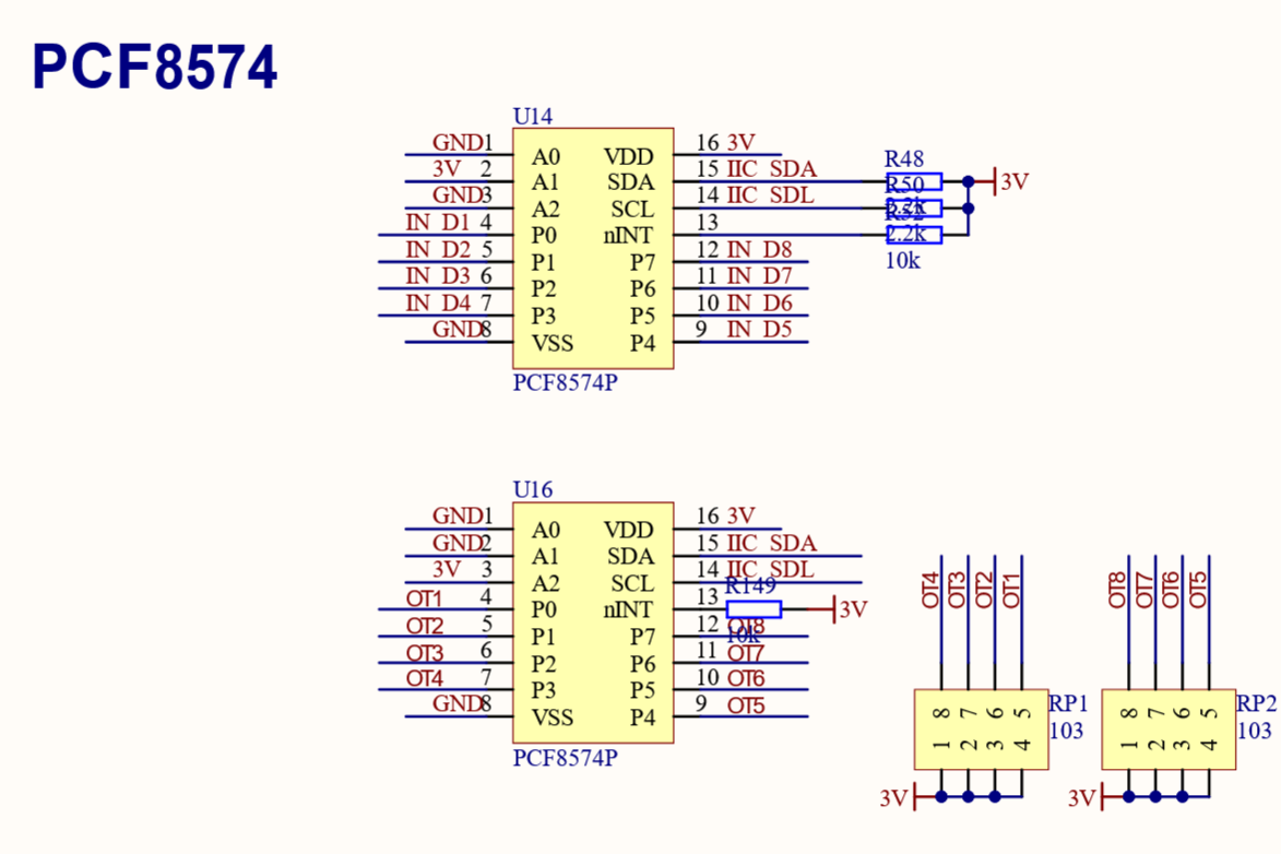
You can see that the expcted I2C address suffic of the port expanders are (A2, A1, A0) = (0,1,0) [aka 0x02) and (1,0,0). [aka 0x04]), the prefix coming from the datasheet
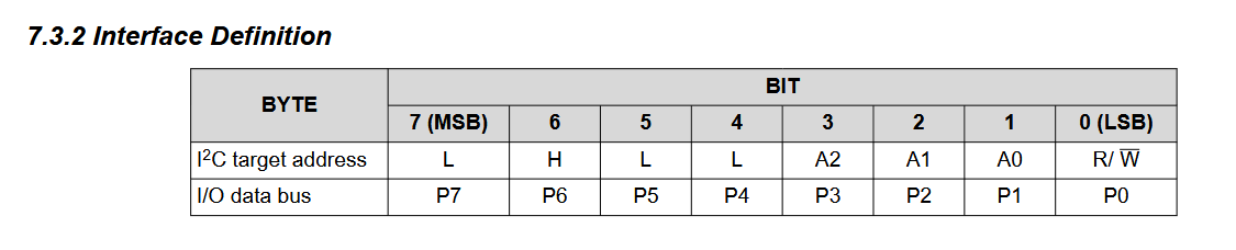
Woudl result in the 7-bit address of the input expander as 0x22 and of the output expander as 0x24.
Why don’t you try a much simpler Arduino firmware that has a premade library for the GPIO expander to see if you can get any LED blinking at all from the expander connected to the output pins?
[env:kc868-A16]
platform = espressif32@6.12.0
board = esp32dev
framework = arduino
monitor_speed = 115200
lib_deps =
  robtillaart/PCF8574@^0.4.4
with src/main.cpp
#include <Arduino.h>
#include "PCF8574.h"

PCF8574 PCF_Input(0x22);
PCF8574 PCF_Output(0x24);

static uint8_t outputState = 0x00;

void setup() {
  Serial.begin(115200);
  Serial.println(__FILE__);
  Serial.print("PCF8574_LIB_VERSION:\t");
  Serial.println(PCF8574_LIB_VERSION);

  Wire.begin(4, 5);

  if(!PCF_Input.begin()) {
    Serial.println("PCF_Input failed to initialize!");
    while (1);
  }
  if(!PCF_Output.begin()) {
    Serial.println("PCF_Output failed to initialize!");
    while (1);
  }
}

void loop() {
    // read all 8 inputs of input PCF
    uint8_t inputState = PCF_Input.read8();
    Serial.print("Input State: 0b");
    // write in binary with leading zeros
    for(int i = 7; i >= 0; i--) {
      Serial.print((inputState & (1 << i)) ? '1' : '0');
    }
    Serial.println();
    // toggle all outputs of periodically
    outputState = ~outputState;
    PCF_Output.write8(outputState);
    Serial.print("Output State set to: 0b");
    Serial.println(outputState, BIN);
    delay(1000);
}