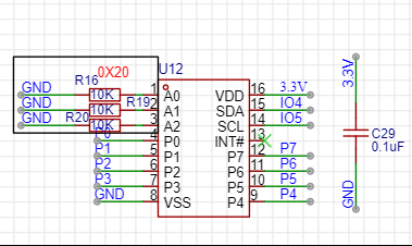
hello!i have one pcf8574 expander,and this is schematic diagram:
and when it work, i want P3 output high level, but the P3 voltage only 0.48v, when P3 output low level, the P3 voltage is 0V, Is this normal? I don’t think it should be that way. why is the high level voltage voltage not greater than or equal to the VDD voltage? Thank you for any help
this is code, and PCF8574.h from [GitHub - RobTillaart/PCF8574: Arduino library for PCF8574 - I2C IO expander]
hello maxgerhardt, between VDD and VSS voltage is 3.3v, this code can control pcf8574, The P3 pin voltage switches between 0V and 0.48V at an interval of 2 seconds,
However, when PCF_20. write(3, HIGH); is executed, the P3 pin is high level and the voltage is 0.48V, not 3.3v
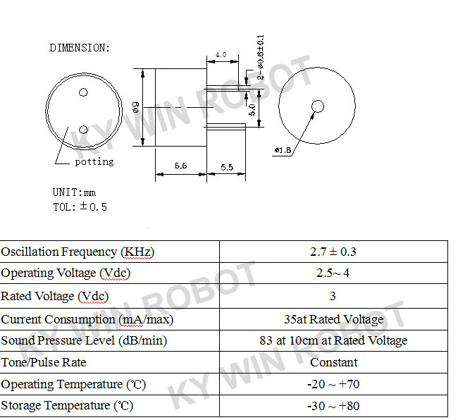
Hello, The P3 pin is only connected to a buzzer TMB09A03. TMB09A03 can be driven by 3V voltage, but the output voltage of the P3 pin is only 0.48V when setting high level, which is not enough to drive the buzzer of TMB09A03
And PCF8574 other pins have been detected using a multimeter and appear to have no problems, , , ,
Then when outputting a high-level, the allowed sourced current in push-pull mode (no pullup activated) is only 0.3mA (I_OH), when outputting a low-level it is a maximum of 25mA sinking current (I_OL). However, both values are less than the maximum current consumption of the buzzer, meaning you cannot drive a buzzer with the PCF8574 chip.
So it looks to me as if you have an electrical problem, trying to source a lot more current (since you set output to HIGH) than the allowed measly 0.3mA. Trying to source more current than allowed makes the output voltage collapse.
You could solve this by only having the PCF8574 only switch on a transistor that can then source more current.
You can also see that in TI’s applicaiton note, the chip is always use to SINK current, i.e. output LOW where it can sink 25mA, or 50mA when using two chips together, but not to SOURCE a lot of current which would happen when you output HIGH.
hello, thanks, but the P3 pin voltage only 0.48V when high level, That’s the main problem, Of course, the current is not enough to drive is also a problem, thanks for the correction,
and i don’t konw When the PCF8574 pin is high level, is it normal that the output voltage is only 0.48V, There is no description of IO output voltage when I read the document
Oh, y … the buzzer has been damaged. I connected a PCF8574 separately with the flying wire for testing and everything was normal, but the high level on the PCB was still only 0.48V. When I removed the buzzer, everything returned to normal,hell,No doubt I had blundered again
thanks a lot
Had the same problem with PCF8574 on a custom circuit board. After reading carefully through the datasheet - it looks like the problem is the idea of “quasi-bidirectional IO”. I can see some applications for it, but in a nutshell - the HIGH output has to be extremely wimpy to be easily overcome by any LOW input.
TI chip datasheet says you can have 4ma from HIGH pin. I used NXP’s chip, that one by the datasheet gives only 100µA on HIGH. So, no surprise here: 10K to ground drops the voltage that much.
So, it only outputs reasonable current when it’s LOW. If you have to drive a load (up to 50mA by the TI specs, 25mA per port and 80mA per chip by NXP) - connect it to VCC directly and drive it with LOW signal from the chip. Conveniently it defaults to all HIGH output. This might be not very convenient to drive N-MOSFETs, so I am looking at a different chip.
And just a data point: with VSS=3.3v and 10K pulldown resistors at the output pins, the HIGH voltage is ~0.9V. It’s THAT wimpy.
So, another observation is that with this chip you would never need pull-up or pulldown resistors as there is always an output - it is never actually in high resistance mode like chips that have ‘Input’ mode.
NXP’s datasheet has quite in-depth explanation of this quasi-bidirectional IO applications and limitations. But who reads those boring datasheets, right?