I have a strange problem with a custom board based on the MK20DX64VLH7 which is the same MCU as a Teensy 3.2. The Teensy 3.2 MCU is 256K Flash/64K RAM (MK20DX256VLH7 and this one is 64K.Flash/16K RAM. Everything else is identical.
The problem is that the same test code will run fine on a a 256K MCU but not on a 64K part. The issue is if I have some String and integer statements in setup() the 64K case “crashes” where the 256K part runs fine. If I comment out the String statement, it runs on the 64K MCU as well.
I have the custom board set up with a JTAG/SWD connector and am using a JLink programmer/debugger. I have loaded code from within PIO as well as directly with the JLink and get the same results. I have tried to use the debugger but have not been able to find the problem.
I suspect the problem is in my board json file and/or linker script but I have researched this a lot and can’t see what is wrong. These files are shown below. (Sorry… I can’t upload the files or figure out how to show them as code)
Any advice on what could be wrong would be greatly appreciated.
Well if the 256K flash device also has 4 times the RAM, the sammer device inherently can’t run all sketches. In Arduino and the String class e.g., the data is stored on the heap, so modifying a large string will create a temporary copy of it RAM, significantly increasing memory usage.
Does the firmware start at all, or does it just crash when you request an operation on a large string? What code are you using for testing?
I should have stated there is a lot of RAM space available, i.e .buinding in release mode, PIO reports
RAM: [=== ] 30.9% (used 5064 bytes from 16384 bytes)
Flash: [======= ] 66.4% (used 43540 bytes from 65536 bytes)
built in debug mode:
RAM: [=== ] 30.8% (used 5052 bytes from 16384 bytes)
Flash: [======= ] 71.8% (used 47072 bytes from 65536 bytes)
Also, the the section of code I was referring to is this:
String xsn = 12;
int xserialNum = xsn.toInt();
and commenting out the second line allows it to “work”. When it fails, the code starts and hangs while executing some library code. I tried it again using the debugger and clicked pause to see where it was hung. It is in the teensy core file mk20dx128.c in the function fault_isr(). in this section of code:
while (1) {
	// keep polling some communication while in fault
	// mode, so we don't completely die.
	if (SIM_SCGC4 & SIM_SCGC4_USBOTG) usb_isr();
	if (SIM_SCGC4 & SIM_SCGC4_UART0) uart0_status_isr();
	if (SIM_SCGC4 & SIM_SCGC4_UART1) uart1_status_isr();
	if (SIM_SCGC4 & SIM_SCGC4_UART2) uart2_status_isr();
}
Interestingly, I do have a USB cable connected for a serial monitor function but there is no code using it
in this test. I unplugged the cable and got the same result… The isr that is being repeatedly called is usb_isr.
One other piece of information is that when I said it runs with a 256K MCU, that was on a Teensy 3.2 not with my custom board with a 256K MCU. I have used this custom board design with 128K and 256K MK20’s and have not seen this problem. However, I am going to build another version of this exact board with a 256K part and see if I have the same problem.
I agree it doesn’t seem to have anything to do with the string and int statements in setup(). This is why this has been driving me crazy for 3+ days now! I appreciate your help in resolving this.
As a test, I went back to a previous version of the library I had used in another project with almost the same hardware just to be sure there wasn’t a regression in the updates. The problem was still there. Interestingly, the function where the fault originated was a completely different function.
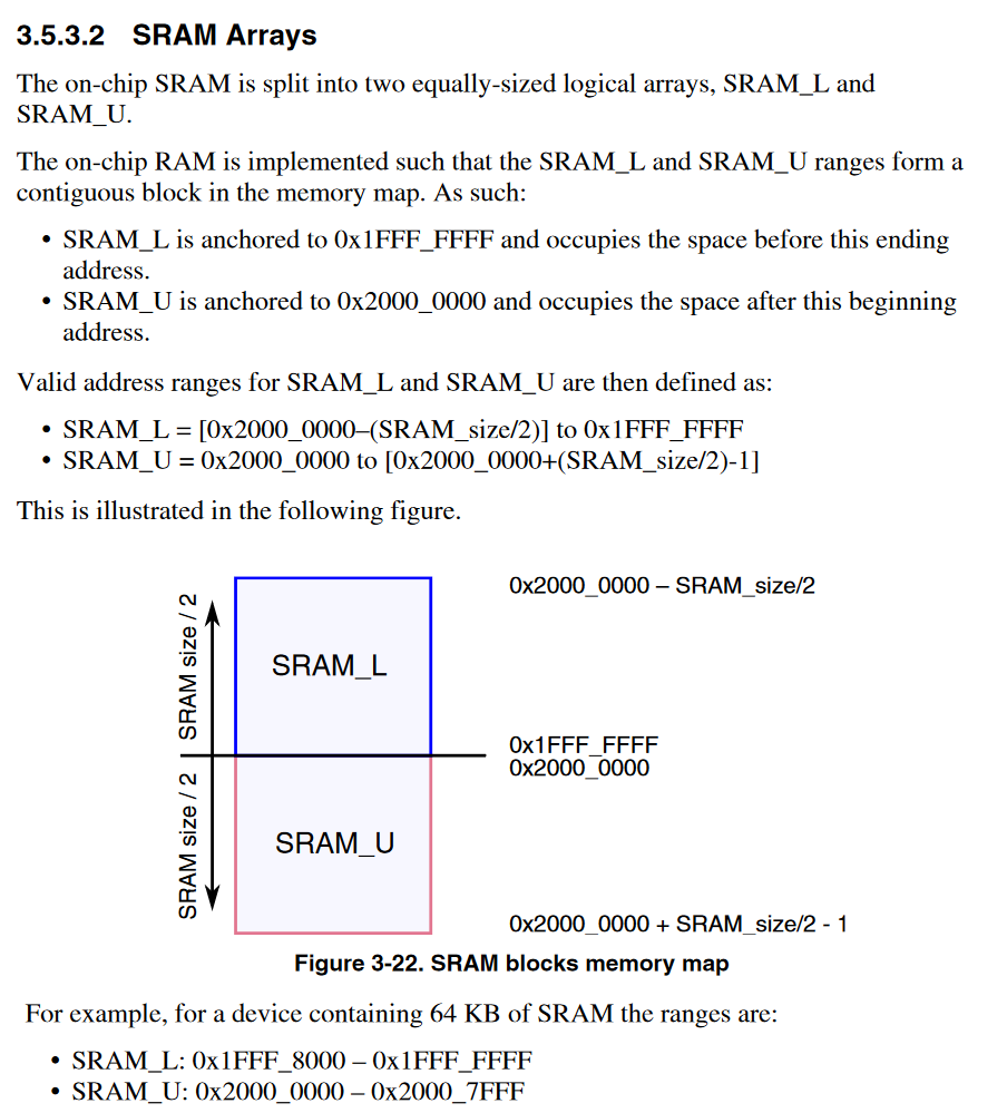
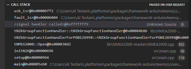
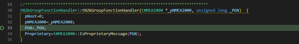
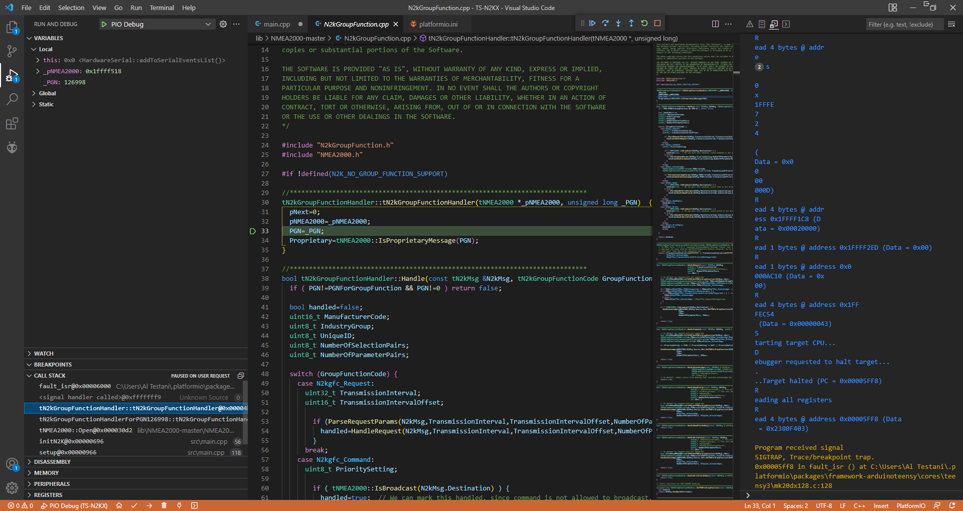
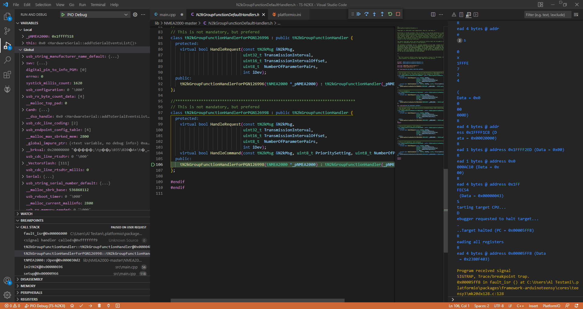
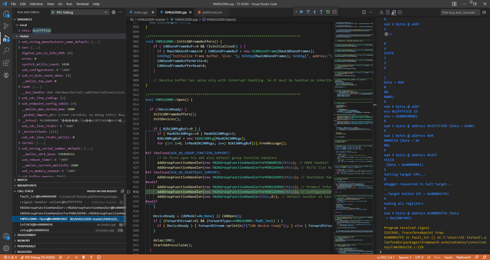
Hm I think I’m starting to see the bigger picture. The Open() function that is in the stacktrace does a number of dynamic allocations with new (source) and the constructed object’s constructor is called. The constructed classes all inherit from the tN2kGroupFunctionHandler handler whose base constructor is called. The code seems to crash when trying to assign something to member variable. This might indicate that the allocated memory for the new-ed object is invalid (e.g. there’s a problem with the heap allocation / sbrk() routines in the case of the 16KB SRAM MCU) or it has already run out of memory and new returned a nullptr and it went and tried to call the constructor code with this = 0x0.
The line tN2kGroupFunctionHandlerForPGN126464 indicates it has gotten past the first allocation (tN2kGroupFunctionHandlerForPGN60928()) and is stuck in that next allocation (new tN2kGroupFunctionHandlerForPGN126464(this)). But it may already have been just luck that it has gotten through the first one if the heap is broken.
The debugger on the left side should show the values of the variables in the content. Can you post the full VSCode screenshot for each of the 3 functions in the call stack below the <signal handler called>?
Would it help if you connected to my machine with AnyDesk or TeamViewer and watched this happening live? I am more than happy to do that if you are willing.
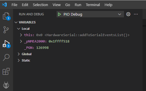
Yeah that’s already game over. this = 0x0 should not happen.
I have to look at the memory allocation routines and possibly the linker script on why that might happen.
Can you write a minimal firmware that just does allocations in a loop with malloc() of let’s say, 512 bytes, and prints out the returned pointer and breaks out when it’s 0? After what number of allocations does that happen? I’m trying to distinguish whether you’re experiencing an out-of-memory because the sketch (or rather, this nice library you’re using) allocates a bazillion bytes on the heap or whether the heap is outright broken.
I’m not very good with pointers so I apologize if I don’t have this right but here is what I got with the sketch below. I expected to see the first address to be something close to 0x1fffffe000, like 0x1fffe414 to account for the globals and the first allocation.
Edit: I commented out the char x[512] and did malloc(512) directly and got the same result.
Well so after 5 allocations we already can’t allocate the next 512 bytes, so in this example with very minimal static RAM usage you’re only getting 2560 bytes from the heap before it says ‘nope’. The library states
With default settings library requires about 23 kB rom and 3.3 kB RAM in normal operation
So the heap gives you less than the stated RAM memory requirements of the library. That’s bad. Sketches who allocate more static memory (in e.g. global, statically constructed objects) will have an even smaller amount of heap memory available then.
The -D__MK20DX256__ is not good, it tells the core that it’s the wrong type of chip. Based on this macro, it does certain decisions. Most interestingly, although the Teensy 3.2 is a MK20DX256VLH7, it still has provisions for the 128K device?
You see that for the currently active macro, __MK20DX256__, it uses a STACK_MARGIN of 4096 bytes. This STACK_MARGIN is used as the maximum number of bytes allowable between the heap that starts at the _ebss (end of BSS section, see linker script) and current stack pointer (evaluated dynamically). Probably because the __MK20DX256__ has 4 times the RAM, they chose the safety margin between heap and stack (so that they don’t collide) 4 times as big as computed to the __MK20DX128__ case.
I would recommend that in your custom board definition file you exchange the -D__MK20DX256__ for -D__MK20DX128__. Then at least the core should act like you have 16kBytes of RAM and not 64kBytes. How many allocations can you do then with the same sketch as before?
Thanks!! Now it is all making sense! In a past project, I used a 128K RAM MK20 with the -D_MK20DX256 flag and it worked. From that I incorrectly (stupidly, I guess) assumed that flag didn’t matter for the general MK20 family.
Anyway, I tried using the MK20DX128 flag and for some reason I lost the serial monitor but I added an LED to “count” allocations and found it went from 6 to 15 which is getting about 5K back as expected.
I didn’t follow-up to find out why the serial port went away. Instead, I went back to the 256K flag and started editing mk20dx128.c and changed the stack margin to 1024 for that flag. Look what I got… it is now using the other SRAM bank!
I went back to my test program and with the change to mk20dx128.c, that works now. The real application now works as well.
So now the question is how do I use this “special” version of mk20dx128.c ?? I don’t want to modify the platform. I changed mk20dx128.c back to original and put the edited version in the project src folder. That seems to work. Is doing it that way legitimate?
Well since the code is using that you can also just add a specific value definition to that with build_flags, .i.e, build_flags = -DSTACK_MARGIN=1024. You can also put it in the extra_flags of your board definition if you always want to use that with the board. Then no framework files have to be modified.