I was doing a pwm and I noticed my cpu is running around 12 Mhz or slower. So I started reading and only ended up more confused that I started.
why can’t I use menuconfig?
PS C:\Users\Administrator\Desktop\usb2llapi\usb_host_lib> pio run -t menuconfig
pio : The term ‘pio’ is not recognized as the name of a cmdlet
2)is there a way to use ESP.getCpuFreqMHz() I can not figure out how to use ESP or know what include to use.
Does ESP use either external or internal clocks? IS there a way to set that on one of the DEVKITC boards?
Yes agreed. I was rather confused to see this result. Perhaps I’m missing something simple then. I’m not looking for anyone to do my work for me, I just wanted the tools to figure out what I’m doing wrong. Since you ask… I worked with STm32’s before and used the same approach to test speed.
unless I’m missing something there is no way 2 clocks are going to be that slow. I say two clocks because I know AVR takes two, but I have not checked the assemble on the esp32 for changing a pin state…
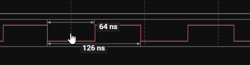
1000 / 16 gives me 62 ns
1000 / 240 gives me 4 ns as to why I’m confused.
1000 / 4 gives me 250 ns, so its not even going that fast?
I am using a
xTaskCreate(&Start_LLAPI, “”, 2048, NULL, 5, NULL);
to kick off my test. I do not have to but I was in the middle of learning when I saw this issue. So I could remove it.
Another question I had that I didn’t get to yes was. what xTaskCreate does. I know this chip has dual cores and I read it does not have threads. So I was curios if it had hyper threading. There are times I will need to do two things at once but do not need exclusive CPU time. I thought that is what xTaskCreate did. I will at other times ( not currently ) need to understand how to put a task on another core. Not looking to load up this thread on my backlog but it is sort of related.
In general I find it very hard to get info on this chip, the net is very polluted on it, esp32 seems useless and never replies, and this form seem to have the only good content. I learn most of what I need on my own but it takes some effort compare to most chips.
That gpio_set_level doesn’t compile to a single insturction. It goes through 2 levels of abstraction and some if() statements before reaching the actual hardware register to write to. So judging the pulse width of that signal doesn’t tell you much about the clock speed, it just tells you about how inefficiently the ESP32 is programmed.
Plus the ESP32S3 is running an RTOS, so it will get periodically interrupted by to reschedule another task, for example for processing the WiFi, stealing processing time from you.
A slightly fairer comparison would be if you used direct register writes
while ( 1 )
   {
    vTaskDelay( 1000 / portTICK_PERIOD_MS);
   GPIO.out_w1ts = (1 << 2); // set GPIO2 HIGH
   GPIO.out_w1tc = (1 << 2); // set GPIO2 LOW
   // avoid overhead of jumping back to the top of the loop by injecting the code again
   GPIO.out_w1ts = (1 << 2); // set GPIO2 HIGH
   GPIO.out_w1tc = (1 << 2); // set GPIO2 LOW
   GPIO.out_w1ts = (1 << 2); // set GPIO2 HIGH
   GPIO.out_w1tc = (1 << 2); // set GPIO2 LOW
   GPIO.out_w1ts = (1 << 2); // set GPIO2 HIGH
   GPIO.out_w1tc = (1 << 2); // set GPIO2 LOW
  }
ok or I could just use ASM… but good to know, BTW, is there a RTOS free code swtich? At some point I will want to get very accurate timing with my code. My goal is not to always use ASM, I like to be able to read my code. But I do write a lot of sensitive stuff. Is there any
DISABLE_RTOS
do this
ENABLE_RTOS
also do you have a link to the GPIO.out_w1tc reference. I will lily need to see how port direction works too.
Thx for the info, all very helpful.
edit:
WOW, I’d not call that fair. Sure it twiddles the pins as fast as my avr but we are comparing 16 to 240 MegaHertz here.
Just surprising there are no commands that are free from so much overhead. Regardless better then it was. I’m also not sure the pin status works anything like I’m thinking. Can I use GPIO.status_w1ts like a mask for the input configuration modes?
Like
if ( GPIO.status_w1ts & 5)… pins 0 and 2 are high?
Is any other FreeRTOS task stealing processing time from you?
Try that full sketch
#include <Arduino.h>

void setup() {
  pinMode(2, OUTPUT);
}

void loop() {
   noInterrupts();
   GPIO.out_w1ts = (1 << 2); // set GPIO2 HIGH
   GPIO.out_w1tc = (1 << 2); // set GPIO2 LOW
   // avoid overhead of jumping back to the top of the loop by injecting the code again
   GPIO.out_w1ts = (1 << 2); // set GPIO2 HIGH
   GPIO.out_w1tc = (1 << 2); // set GPIO2 LOW
   GPIO.out_w1ts = (1 << 2); // set GPIO2 HIGH
   GPIO.out_w1tc = (1 << 2); // set GPIO2 LOW
   GPIO.out_w1ts = (1 << 2); // set GPIO2 HIGH
   GPIO.out_w1tc = (1 << 2); // set GPIO2 LOW
   interrupts();
}
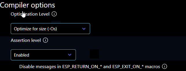
Wait so are you using PlatformIO at all or pure ESP-IDF? Do you have ESP-IDF setup to use compiler optimization then?
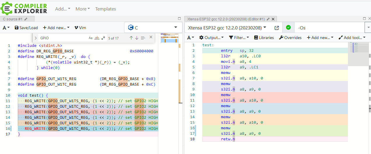
And the code above there is still suboptimal. It loads the GPIO device from RAM once. You want to actually do pure register writes
   REG_WRITE(GPIO_OUT_W1TS_REG, (1 << 2)); // set GPIO2 HIGH
   REG_WRITE(GPIO_OUT_W1TC_REG, (1 << 2)); // set GPIO2 LOW
   REG_WRITE(GPIO_OUT_W1TS_REG, (1 << 2)); // set GPIO2 HIGH
   REG_WRITE(GPIO_OUT_W1TC_REG, (1 << 2)); // set GPIO2 LOW
   REG_WRITE(GPIO_OUT_W1TS_REG, (1 << 2)); // set GPIO2 HIGH
   REG_WRITE(GPIO_OUT_W1TC_REG, (1 << 2)); // set GPIO2 LOW
(should work fine witih just #include <soc/gpio_reg.h> or only the standard includes)
The optimized (-Os) output is just the pure store instruction and a memw (“memory wait”) instruction.
MEMW ensures that all previous load, store, acquire, release, prefetch, and cache instructions
along with any writebacks caused by previous cache instructions perform before performing
any subsequent load, store, acquire, release, prefetch, or cache instructions. MEMW is
intended to implement the volatile attribute of languages such as C and C++. The compiler
should separate all volatile loads and stores with a MEMW instruction
register read and write maybe what I was hoping for I can try it.
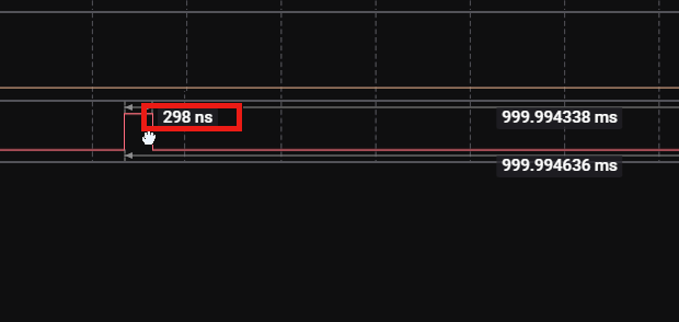
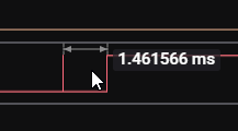
UPDATE: Not sure what I could be doing wrong. here. I know the compile opt. worked because it did want to fully recompile after I set it. I also tried to use the dirrect write but still seeing 60nS. I may have to check my scope, its only 100 MHz (500 Msamples/secons) so that maybe my bottle neck ( pending doing the math) .Press sure that gives me better resolution then 60nS. 100 MHz = 10 ns right?
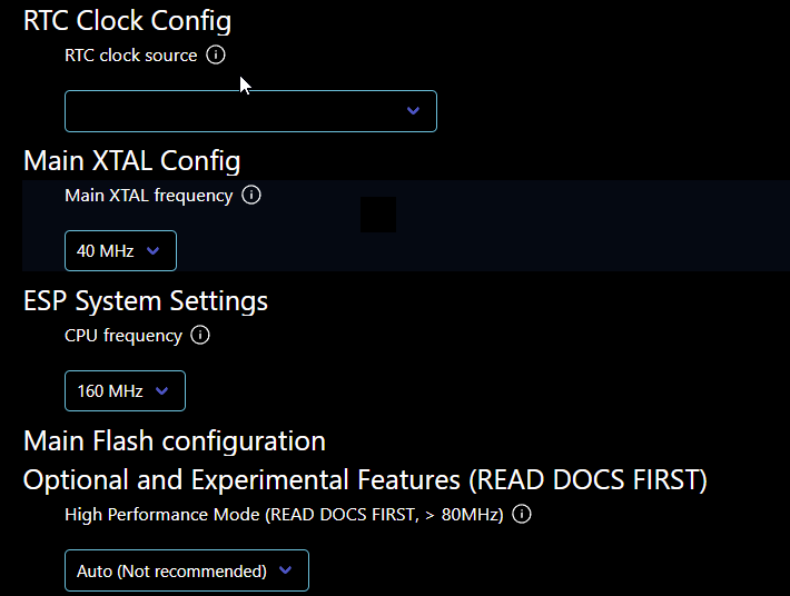
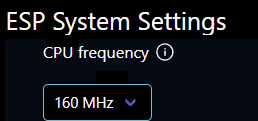
From the settings I tried changing the ESP system settings CPU freq to 240 but no change.
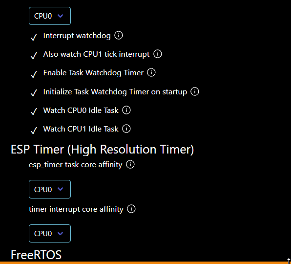
I thought we could put code on a certain cpu some how? I think that woudl work best but can’t figure it out.
UPDATE: Just found this
If you start up a task using the FreeRTOS xTaskCreate function, FreeRTOS will automatically run the task on any of the two CPUs, whichever one is free. You can also ‘pin’ a task to one single CPU by using xTaskCreatePinnedToCore.
yeah I thought the was weird I wonder why the example from esp-idf had that?
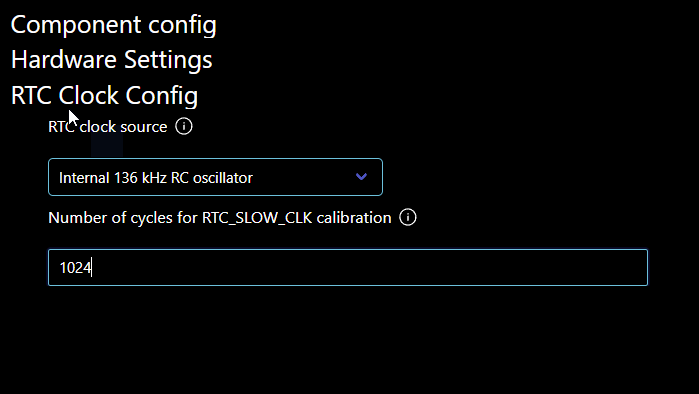
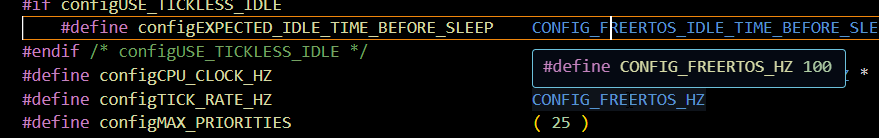
its in the sdkconfig.h file.
Every time I change it, and build it goes back to 100
this is the chain
vTaskDelay(2 / portTICK_PERIOD_MS); //mainn app #define portTICK_PERIOD_MS ( ( TickType_t ) 1000 / configTICK_RATE_HZ ) // FreeRTOS-Kernel\portable\xtensa\include\freertos\portmacro.h #define configTICK_RATE_HZ CONFIG_FREERTOS_HZ// freertos\FreeRTOSConfig.h #define CONFIG_FREERTOS_HZ 100 //sdkconfig files can not change.
The sdkconfig.h file will be autogenerated from the sdkconfig file which is supposed to be configured with the GUI tool. So you have to find the setting in there.