I was tinkering with an ATtiny1604 based project with a possible bug. Previously, I had to do a conditional compile to either have my last pin control and LED (on production unit) or generate debug serial output - but not both at once as I had run out of pins.
Not ideal so I went hunting for an alternative.
What if I could use the UPDI pin as a general GPIO pin and have this send serial debug data out.
To achieve this I followed instructions at Tiny UPDI-HV Programmer.
I also found a SendOnlySoftwareSerial library by Nick Gammon that takes the Arduino pin number as the TX pin - on an ATtiny1604, this equates to pin 11. This can be found at Send-only Software Serial.
Here’s a picture of the PlatformIO library setup.

Before I could get the ATtiny1604 to send serial data on any pin, I had to tune the clock as per Internal oscillators and Tuning on Tiny AVR devices.
I hooked it all together and it eventually worked but I had to swap out the UPDI programmer with a serial convertor which seemed a faf as I was using the same serial convertor for my UPDI programmer. I also found that I needed to power reset the target device after HV programming to get it to use the UPDI pin as a GPIO pin for the serial data output.
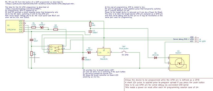
I modified the original HV UPDI concept slightly to include a 12v source (boost circuit) selectable by pressing a push button while starting the UPDI programming sequence and added a MOSFET on the power out to target. This was controlled by an RC and diode link that generated a positive pulse briefly when the DTR signal from the serial board went back to Vcc after programming was complete.
The net effect is I can run a monitor within PlatformIO on the same port as the programming port and the target device will power on reboot after programming and start using the same port (no need to disconnect anything) for serial data output.
OK the PlatformIO switch over time from upload to monitor means I miss the output from setup() but I can live with that or introduce a delay.
Here’s my PlatformIO.ini
; PlatformIO Project Configuration File
;
;   Build options: build flags, source filter
;   Upload options: custom upload port, speed and extra flags
;   Library options: dependencies, extra library storages
;   Advanced options: extra scripting
;
; Please visit documentation for the other options and examples
; https://docs.platformio.org/page/projectconf.html

[env:ATtiny1604]
platform = atmelmegaavr
board = ATtiny1604
framework = arduino
board_build.f_cpu = 16000000L
upload_speed = 115200
upload_port = COM16
monitor_port = COM16
monitor_speed = 115200
upload_flags =
    --tool
    uart
    --device
    ATtiny1604
    --uart
    $UPLOAD_PORT
    --clk
    $UPLOAD_SPEED
upload_command = pymcuprog write --erase $UPLOAD_FLAGS --filename $SOURCE
Here’s my sample code…
// ATtiny1604_Serial_on_UPDI_pin
// written for ATtiny1604
// Peter Charles-Jones
// cSpell:includeRegExp CStyleComment

/* 	MCU clock tuning

	Device was tuned to 16M <https://github.com/SpenceKonde/megaTinyCore/blob/master/megaavr/extras/Ref_Tuning.md>
	First the device had a bare bones sketch loaded using Arduino IDE and a boot loader burnt at 16M with Millis disabled
	Then the MegaTinyTuner example sketch was loaded into target and run with a 1kHz source connected to PA5
	Then the boot loader was re-loaded with 16M tuned selected as clock
*/

#include <Arduino.h>
#include <SendOnlySoftwareSerial.h>		//
#define BAUD 115200						// serial comms baud rate
SendOnlySoftwareSerial mySerial (11);	// set up the serial output stream to PA0 - UPDI pin
//SendOnlySoftwareSerial mySerial (5);	// set up the serial output stream to PB1 - test on another pin first


// You can initialise like this: RH_ASK driver(2000, 6, 7); which will transmit on digital pin 7 == PB0 == physical pin 9 on Attiny x14 and receive on digital pin 6 == PB1 == physical pin 8 on Attiny x16 Uses Timer B1.

/* 	Pin numbering scheme

	This core uses a simple scheme for assigning the Arduino pin numbers:
	Pins are numbered starting from the the I/O pin closest to Vcc as pin 0
	and proceeding counterclockwise, skipping the (mostly) non-usable UPDI pin.
	The UPDI pin is then assigned to the last pin number (as noted above, it is possible to read the UPDI pin
	(both analog and digital reads work) even if it is not set as GPIO).
	We recommend this as a last resort: the UPDI pin always has its pullup enabled when not set as a GPIO pin,
	and a signal which looks too much like the UPDI enable sequence will cause undesired operation.*/

// ATtiny1604 / ARDUINO
//                          _____
//                  VDD   1|*    |14  GND
// (nSS)  (AIN4) PA4  0~  2|     |13  10~ PA3 (AIN3)(SCK)(EXTCLK)
//        (AIN5) PA5  1~  3|     |12  9   PA2 (AIN2)(MISO)
// (DAC)  (AIN6) PA6  2   4|     |11  8   PA1 (AIN1)(MOSI)
//        (AIN7) PA7  3   5|     |10  11  PA0 (nRESET/UPDI)
// (RXD) (TOSC1) PB3  4   6|     |9   7~  PB0 (AIN11)(SCL)
// (TXD) (TOSC2) PB2  5~  7|_____|8   6~  PB1 (AIN10)(SDA)
//

/*
  PIN#   DESC         Pin Name  Other/Sp  ADC0      ADC1      PTC       AC0       AC1       AC2       DAC0      USART0    SPI0      TWI0      TCA(PWM)  TCBn      TCD0      CCL
  0      A0 or SS     PA4                 AIN4      AIN0      X0/Y0                                             XDIR      SS                  WO4                 WOA       LUT0-OUT
  1      A1           PA5       VREFA     AIN5      AIN1      X1/Y1     OUT       AINN0                                                       WO5       TCB0 WO   WOB
  2      A2 or DAC    PA6                 AIN6      AIN2      X2/Y2     AINN0     AINP1     AINP0     OUT
  3      A3           PA7                 AIN7      AIN3      X3/Y3     AINP0     AINP0     AINN0                                                                           LUT1-OUT
  4      RX           PB3       TOSC1                                             OUT                           RxD                           *WO0
  5      TX           PB2       TOSC2 /                                                     OUT                 TxD                           WO2
								EVOUT1
  6      SDA          PB1                 AIN10               X4/Y4     AINP2                                   XCK                 SDA       WO1
  7      SCL          PB0                 AIN11               X5/Y5               AINP2     AINP1               XDIR                SCL       WO0
  8      MOSI         PA1                 AIN1                                                                  *TxD      MOSI      *SDA                                    LUT0-IN1
  9      MISO         PA2       EVOUT0    AIN2                                                                  *RxD      MISO      *SCL                                    LUT0-IN2
  10     SCK          PA3       EXTCLK    AIN3                                                                  *XCK      SCK                 WO3       TCB1 WO
  11     UPDI         PA0       RESET/    AIN0                                                                                                                              LUT1-IN0
							    UPDI
	* alternative pin locations
  */

// put function declarations here:
void system_init();

void setup(){
	system_init();
	mySerial.begin(BAUD);
	mySerial.println(F("\r\n\r\nStarting"));
	}

void loop(){
	mySerial.println(F("Hello"));
	delay(500);
}

/* My subroutines */

/* Interrupt Service Routines */

/* Initialization routines */
void mcu_init(void){
	/* On AVR devices all peripherals are enable from power on reset, this
	 * disables all peripherals to save power. Driver shall enable
	 * peripheral if used */

	/* Set all PORTA pins to low power mode and input disabled */
	for (uint8_t i = 0; i < 8; i++)
	{ // PA0 - PA7
		//*((uint8_t *)&PORTA + 0x10 + i) |= (1 << PORT_PULLUPEN_bp);
		uint8_t *port_pin_ctrl = ((uint8_t *)&PORTA + 0x10 + i);
		*port_pin_ctrl |= (1 << PORT_PULLUPEN_bp);								   // define pull up
		*port_pin_ctrl = (*port_pin_ctrl & ~PORT_ISC_gm) | PORT_ISC_INTDISABLE_gc; // disable input sensing
	}

	/* Set all PORTB pins to low power mode and input disabled */
	for (uint8_t i = 0; i < 4; i++)
	{ // PB0 - PB3 on ATtiny1604
		//*((uint8_t *)&PORTB + 0x10 + i) |= (1 <<  PORT_PULLUPEN_bp);
		uint8_t *port_pin_ctrl = ((uint8_t *)&PORTB + 0x10 + i);
		*port_pin_ctrl |= (1 << PORT_PULLUPEN_bp);								   // define pull up
		*port_pin_ctrl = (*port_pin_ctrl & ~PORT_ISC_gm) | PORT_ISC_INTDISABLE_gc; // disable input sensing
	}
}

void system_init(){ /* system initialization */
	mcu_init();
}
A picture of the circuit.
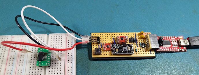
And a photo of the built programmer
I hope this helps anyone stuck for a pin to provide some serial debug output.

