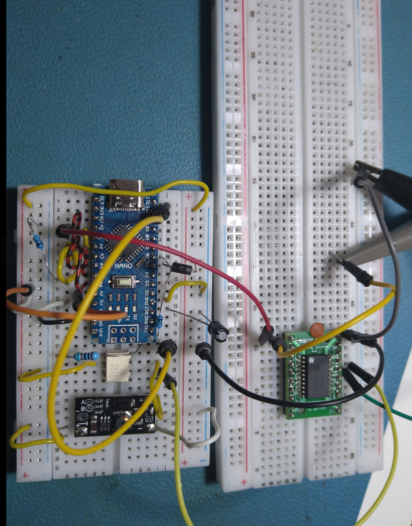
With a prompt from Hans Meijdam, I built the HV UPDI programmer he suggested < DIY HV UPDI Programmer · Dlloydev/jtag2updi Wiki · GitHub >
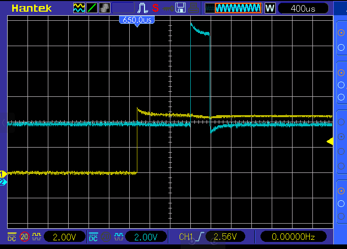
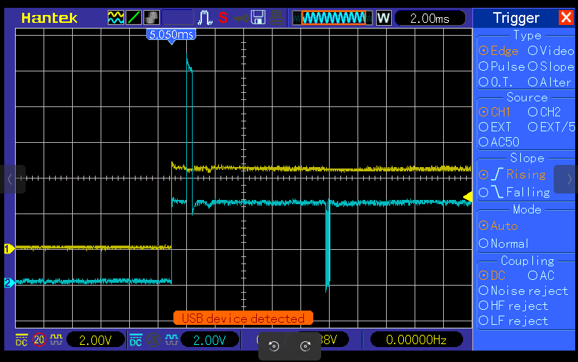
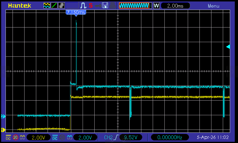
This didn’t work - the supply voltage (yellow) and UPDI voltage (blue) as below:
on a longer time base
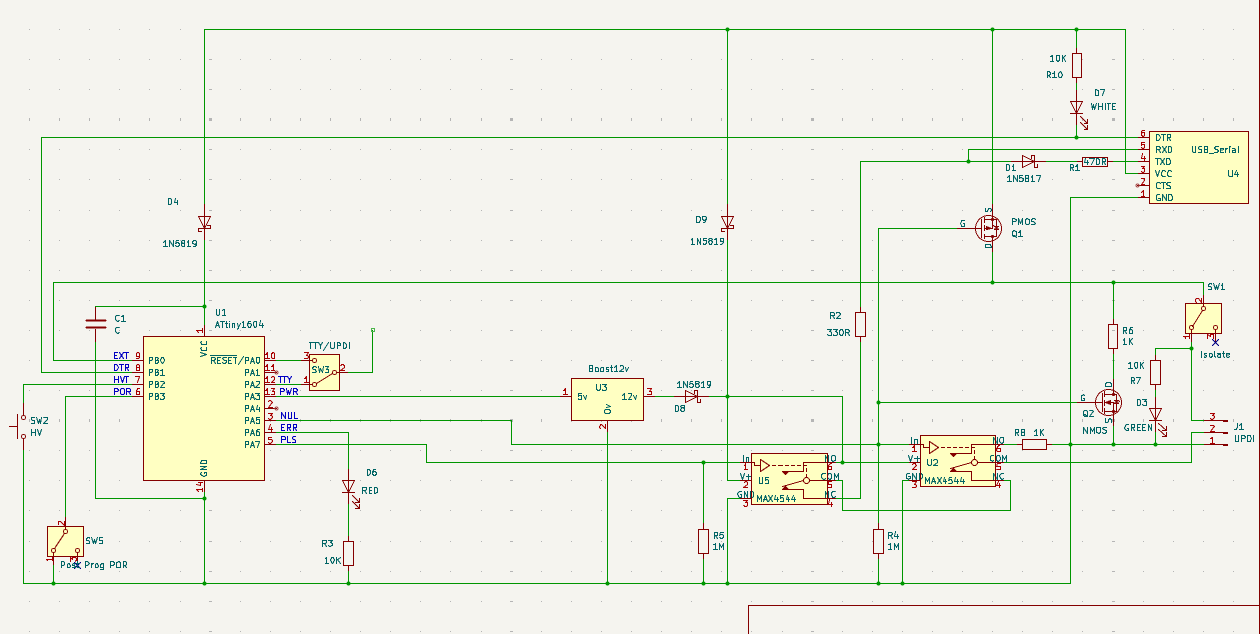
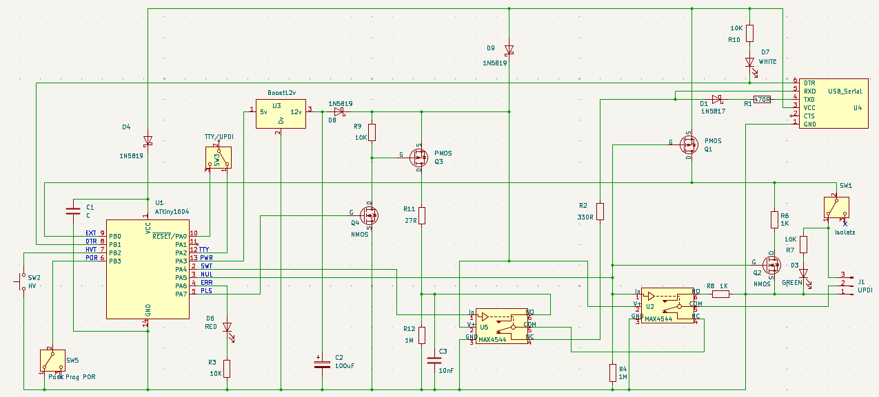
Back to my SerialUPDI modified circuit…
I use an ATtiny1604 so I can accurately time the power on to the target, the 12v pulse start and end.
BTW - while it does a Power On Reset of the target, it also connects the UPDI pin to ground via 1K and just in case there’s a big capacitor on the target supply, it also shorts this via 1K during the POR.
I just bricked another device.
Here’s the above programmer verbose output BEFORE burning UPDI as GPIO (so generally it’s wired up OK)…
Processing ATtiny3226 (platform: atmelmegaavr; board: ATtiny3226; framework: arduino)
------------------------------------------------------------------------------------------------------------------------------------------------------
Verbose mode can be enabled via `-v, --verbose` option
CONFIGURATION: https://docs.platformio.org/page/boards/atmelmegaavr/ATtiny3226.html
PLATFORM: Atmel megaAVR (1.9.0) > ATtiny3226
HARDWARE: ATTINY3226 20MHz, 3KB RAM, 32KB Flash
PACKAGES:
 - framework-arduino-megaavr-megatinycore @ 2.6.7
 - tool-avrdude @ 1.70100.0 (7.1.0)
 - toolchain-atmelavr @ 3.70300.220127 (7.3.0)
LDF: Library Dependency Finder -> https://bit.ly/configure-pio-ldf
LDF Modes: Finder ~ chain, Compatibility ~ soft
Found 15 compatible libraries
Scanning dependencies...
No dependencies
Building in release mode
Compiling .pio/build/ATtiny3226/src/main.cpp.o
Compiling .pio/build/ATtiny3226/FrameworkArduino/ExtraWiring.cpp.o
Compiling .pio/build/ATtiny3226/FrameworkArduino/Tone.cpp.o
Compiling .pio/build/ATtiny3226/FrameworkArduino/UART.cpp.o
Compiling .pio/build/ATtiny3226/FrameworkArduino/UART0.cpp.o
Compiling .pio/build/ATtiny3226/FrameworkArduino/UART1.cpp.o
Compiling .pio/build/ATtiny3226/FrameworkArduino/WInterrupts.c.o
Compiling .pio/build/ATtiny3226/FrameworkArduino/WInterrupts_PA.c.o
Compiling .pio/build/ATtiny3226/FrameworkArduino/WInterrupts_PB.c.o
Compiling .pio/build/ATtiny3226/FrameworkArduino/WInterrupts_PC.c.o
Compiling .pio/build/ATtiny3226/FrameworkArduino/WMath.cpp.o
Compiling .pio/build/ATtiny3226/FrameworkArduino/abi.cpp.o
Compiling .pio/build/ATtiny3226/FrameworkArduino/api/Common.cpp.o
Compiling .pio/build/ATtiny3226/FrameworkArduino/api/IPAddress.cpp.o
Compiling .pio/build/ATtiny3226/FrameworkArduino/api/PluggableUSB.cpp.o
Compiling .pio/build/ATtiny3226/FrameworkArduino/api/Print.cpp.o
Compiling .pio/build/ATtiny3226/FrameworkArduino/api/RingBuffer.cpp.o
Compiling .pio/build/ATtiny3226/FrameworkArduino/api/Stream.cpp.o
Compiling .pio/build/ATtiny3226/FrameworkArduino/api/String.cpp.o
Compiling .pio/build/ATtiny3226/FrameworkArduino/hooks.c.o
Compiling .pio/build/ATtiny3226/FrameworkArduino/main.cpp.o
Compiling .pio/build/ATtiny3226/FrameworkArduino/new.cpp.o
Compiling .pio/build/ATtiny3226/FrameworkArduino/wiring.c.o
Compiling .pio/build/ATtiny3226/FrameworkArduino/wiring_analog.c.o
Compiling .pio/build/ATtiny3226/FrameworkArduino/wiring_digital.c.o
Compiling .pio/build/ATtiny3226/FrameworkArduino/wiring_extra.cpp.o
Compiling .pio/build/ATtiny3226/FrameworkArduino/wiring_pulse.S.o
Compiling .pio/build/ATtiny3226/FrameworkArduino/wiring_pulse.c.o
Compiling .pio/build/ATtiny3226/FrameworkArduino/wiring_shift.c.o
Archiving .pio/build/ATtiny3226/libFrameworkArduino.a
Indexing .pio/build/ATtiny3226/libFrameworkArduino.a
Linking .pio/build/ATtiny3226/firmware.elf
Checking size .pio/build/ATtiny3226/firmware.elf
Advanced Memory Usage is available via "PlatformIO Home > Project Inspect"
RAM:   [          ]   4.9% (used 151 bytes from 3072 bytes)
Flash: [=         ]   6.4% (used 2110 bytes from 32768 bytes)
Building .pio/build/ATtiny3226/firmware.hex
Configuring upload protocol...
AVAILABLE: jtag2updi
CURRENT: upload_protocol = jtag2updi
Looking for upload port...
Using manually specified: /dev/ttyUSB1
Uploading .pio/build/ATtiny3226/firmware.hex
Connecting to SerialUPDI
pymcuprog.programmer - INFO - Setting up programming session for 'attiny3226'
pymcuprog.deviceinfo.deviceinfo - INFO - Looking for device attiny3226
pymcuprog.serialupdi.physical - INFO - Opening port '/dev/ttyUSB1' at 115200 baud (timeout 1.0s)
pymcuprog.serialupdi.physical - DEBUG - send : [0x00]
pymcuprog.serialupdi.link - DEBUG - STCS to 0x03
pymcuprog.serialupdi.physical - DEBUG - send : [0x55, 0xC3, 0x08]
pymcuprog.serialupdi.link - DEBUG - STCS to 0x02
pymcuprog.serialupdi.physical - DEBUG - send : [0x55, 0xC2, 0x80]
pymcuprog.serialupdi.link - DEBUG - LDCS from 0x00
pymcuprog.serialupdi.physical - DEBUG - send : [0x55, 0x80]
pymcuprog.serialupdi.physical - DEBUG - receive : [0x40]


I chopped a bunch out here

pymcuprog.programmer - INFO - Write complete.
pymcuprog.serialupdi.application - INFO - Leaving NVM programming mode
pymcuprog.serialupdi.application - INFO - Apply reset
pymcuprog.serialupdi.link - DEBUG - STCS to 0x08
pymcuprog.serialupdi.physical - DEBUG - send : [0x55, 0xC8, 0x59]
pymcuprog.serialupdi.application - INFO - Release reset
pymcuprog.serialupdi.link - DEBUG - STCS to 0x08
pymcuprog.serialupdi.physical - DEBUG - send : [0x55, 0xC8, 0x00]
pymcuprog.serialupdi.link - DEBUG - STCS to 0x03
pymcuprog.serialupdi.physical - DEBUG - send : [0x55, 0xC3, 0x0C]
Done.
pymcuprog.serialupdi.physical - INFO - Closing port '/dev/ttyUSB1'
============================================================ [SUCCESS] Took 7.62 seconds ===========================================================
And after burning the UPDI pin as GPIO using Arduino 1.8.19 …
Here is the Arduino output…
/home/peter/snap/arduino/85/.arduino15/packages/megaTinyCore/tools/python3/3.7.2-post1/python3 -u /home/peter/snap/arduino/85/.arduino15/packages/megaTinyCore/hardware/megaavr/2.6.10/tools/prog.py -t uart -u /dev/ttyUSB1 -b 230400 -d attiny3226 --fuses 0:0b00000000 1:0x00 2:0x02 5:0b11110011 6:0x04 7:0x00 8:0x00 -aerase -v
SerialUPDI
UPDI programming for Arduino using a serial adapter
Based on pymcuprog, with significant modifications
By Quentin Bolsee and Spence Konde
Version 1.2.3 - Jan 2022
Using serial port /dev/ttyUSB1 at 230400 baud.
Target: attiny3226
Set fuses: ['0:0b00000000', '1:0x00', '2:0x02', '5:0b11110011', '6:0x04', '7:0x00', '8:0x00']
Action: erase
pymcuprog.programmer - INFO - Setting up programming session for 'attiny3226'
pymcuprog.deviceinfo.deviceinfo - INFO - Looking for device attiny3226
pymcuprog.serialupdi.physical - INFO - Opening port '/dev/ttyUSB1' at '115200' baud
pymcuprog.serialupdi.link - INFO - STCS 08 to 0x03
pymcuprog.serialupdi.link - INFO - STCS 06 to 0x02
pymcuprog.serialupdi.link - INFO - LDCS from 0x00
pymcuprog.serialupdi.link - INFO - UPDI init OK
pymcuprog.serialupdi.link - INFO - STCS 06 to 0x02
pymcuprog.serialupdi.link - INFO - Setting UPDI clock to 8 MHz
pymcuprog.serialupdi.link - INFO - STCS 02 to 0x09
pymcuprog.serialupdi.physical - INFO - Switching to '230400' baud
pymcuprog.serialupdi.application - INFO - SIB: 'tinyAVR P:0D:1-3M2 (00.59B0E.0)'
pymcuprog.serialupdi.application - INFO - Device family ID: 'tinyAVR'
pymcuprog.serialupdi.application - INFO - NVM interface: 'P:0'
pymcuprog.serialupdi.application - INFO - Debug interface: 'D:1'
pymcuprog.serialupdi.application - INFO - PDI oscillator: '3M2'
pymcuprog.serialupdi.application - INFO - Extra info: '(00.59B0E.0)'
pymcuprog.serialupdi.application - INFO - Using 16-bit UPDI
pymcuprog.serialupdi.link - INFO - LDCS from 0x00
pymcuprog.serialupdi.application - INFO - PDI revision = 0x04
pymcuprog.serialupdi.link - INFO - LDCS from 0x0B
pymcuprog.serialupdi.link - INFO - LDCS from 0x0B
pymcuprog.serialupdi.application - INFO - Entering NVM programming mode
pymcuprog.serialupdi.link - INFO - LDCS from 0x07
pymcuprog.serialupdi.application - INFO - Apply reset
pymcuprog.serialupdi.link - INFO - STCS 59 to 0x08
pymcuprog.serialupdi.application - INFO - Release reset
pymcuprog.serialupdi.link - INFO - STCS 00 to 0x08
pymcuprog.serialupdi.link - INFO - LDCS from 0x0B
pymcuprog.serialupdi.link - INFO - LDCS from 0x0B
pymcuprog.nvm - INFO - No specific initializer for this provider
Pinging device...
pymcuprog.programmer - INFO - Reading device ID...
pymcuprog.serialupdi.application - INFO - SIB: 'tinyAVR P:0D:1-3M2 (00.59B0E.0)'
pymcuprog.serialupdi.application - INFO - Device family ID: 'tinyAVR'
pymcuprog.serialupdi.application - INFO - NVM interface: 'P:0'
pymcuprog.serialupdi.application - INFO - Debug interface: 'D:1'
pymcuprog.serialupdi.application - INFO - PDI oscillator: '3M2'
pymcuprog.serialupdi.application - INFO - Extra info: '(00.59B0E.0)'
pymcuprog.serialupdi.application - INFO - Using 16-bit UPDI
pymcuprog.serialupdi.link - INFO - LDCS from 0x00
pymcuprog.serialupdi.application - INFO - PDI revision = 0x04
pymcuprog.serialupdi.link - INFO - LDCS from 0x0B
pymcuprog.serialupdi.application - INFO - Device ID from pyupdi = '1E9527' rev 'A'
pymcuprog.nvm - INFO - Device ID: '1E9527'
pymcuprog.nvm - INFO - Device revision: 'A'
pymcuprog.nvm - INFO - Device serial number: 'b'305650334443b69a4c32''
Ping response: 1E9527
Setting fuse 0x0=0x0
Writing literal values...
pymcuprog.programmer - INFO - Write...
pymcuprog.programmer - INFO - Writing 1 bytes of data to fuses...
pymcuprog.programmer - INFO - Write complete.
Verifying literal values...
pymcuprog.programmer - INFO - Reading 1 bytes from fuses...
pymcuprog.programmer - INFO - Verifying...
Action took 0.19s
Setting fuse 0x1=0x0
Writing literal values...
pymcuprog.programmer - INFO - Write...
pymcuprog.programmer - INFO - Writing 1 bytes of data to fuses...
pymcuprog.programmer - INFO - Write complete.
Verifying literal values...
pymcuprog.programmer - INFO - Reading 1 bytes from fuses...
pymcuprog.programmer - INFO - Verifying...
Action took 0.19s
Setting fuse 0x2=0x2
Writing literal values...
pymcuprog.programmer - INFO - Write...
pymcuprog.programmer - INFO - Writing 1 bytes of data to fuses...
pymcuprog.programmer - INFO - Write complete.
Verifying literal values...
pymcuprog.programmer - INFO - Reading 1 bytes from fuses...
pymcuprog.programmer - INFO - Verifying...
Action took 0.19s
Setting fuse 0x5=0xf3
Writing literal values...
pymcuprog.programmer - INFO - Write...
pymcuprog.programmer - INFO - Writing 1 bytes of data to fuses...
pymcuprog.programmer - INFO - Write complete.
Verifying literal values...
pymcuprog.programmer - INFO - Reading 1 bytes from fuses...
pymcuprog.programmer - INFO - Verifying...
Action took 0.19s
Setting fuse 0x6=0x4
Writing literal values...
pymcuprog.programmer - INFO - Write...
pymcuprog.programmer - INFO - Writing 1 bytes of data to fuses...
pymcuprog.programmer - INFO - Write complete.
Verifying literal values...
pymcuprog.programmer - INFO - Reading 1 bytes from fuses...
pymcuprog.programmer - INFO - Verifying...
Action took 0.19s
Setting fuse 0x7=0x0
Writing literal values...
pymcuprog.programmer - INFO - Write...
pymcuprog.programmer - INFO - Writing 1 bytes of data to fuses...
pymcuprog.programmer - INFO - Write complete.
Verifying literal values...
pymcuprog.programmer - INFO - Reading 1 bytes from fuses...
pymcuprog.programmer - INFO - Verifying...
Action took 0.19s
Setting fuse 0x8=0x0
Writing literal values...
pymcuprog.programmer - INFO - Write...
pymcuprog.programmer - INFO - Writing 1 bytes of data to fuses...
pymcuprog.programmer - INFO - Write complete.
Verifying literal values...
pymcuprog.programmer - INFO - Reading 1 bytes from fuses...
pymcuprog.programmer - INFO - Verifying...
Action took 0.19s
Finished writing fuses.
Chip/Bulk erase,
Memory type eeprom is conditionally erased (depending upon EESAVE fuse setting)
Memory type flash is always erased
Memory type lockbits is always erased
...
pymcuprog.programmer - INFO - Erase...
pymcuprog.serialupdi.nvm - INFO - Chip erase using NVM CTRL
Erased.
Action took 0.06s
pymcuprog.serialupdi.application - INFO - Leaving NVM programming mode
pymcuprog.serialupdi.application - INFO - Apply reset
pymcuprog.serialupdi.link - INFO - STCS 59 to 0x08
pymcuprog.serialupdi.application - INFO - Release reset
pymcuprog.serialupdi.link - INFO - STCS 00 to 0x08
pymcuprog.serialupdi.link - INFO - STCS 0C to 0x03
pymcuprog.serialupdi.physical - INFO - Closing port '/dev/ttyUSB1'
The result is another bricked device that will not respond to programmer..
Processing ATtiny3226 (platform: atmelmegaavr; board: ATtiny3226; framework: arduino)
----------------------------------------------------------------------------------------------------------------------------------------------------
Verbose mode can be enabled via `-v, --verbose` option
CONFIGURATION: https://docs.platformio.org/page/boards/atmelmegaavr/ATtiny3226.html
PLATFORM: Atmel megaAVR (1.9.0) > ATtiny3226
HARDWARE: ATTINY3226 20MHz, 3KB RAM, 32KB Flash
PACKAGES:
 - framework-arduino-megaavr-megatinycore @ 2.6.7
 - tool-avrdude @ 1.70100.0 (7.1.0)
 - toolchain-atmelavr @ 3.70300.220127 (7.3.0)
LDF: Library Dependency Finder -> https://bit.ly/configure-pio-ldf
LDF Modes: Finder ~ chain, Compatibility ~ soft
Found 15 compatible libraries
Scanning dependencies...
No dependencies
Building in release mode
Checking size .pio/build/ATtiny3226/firmware.elf
Advanced Memory Usage is available via "PlatformIO Home > Project Inspect"
RAM:   [          ]   4.9% (used 151 bytes from 3072 bytes)
Flash: [=         ]   6.4% (used 2110 bytes from 32768 bytes)
Configuring upload protocol...
AVAILABLE: jtag2updi
CURRENT: upload_protocol = jtag2updi
Looking for upload port...
Using manually specified: /dev/ttyUSB1
Uploading .pio/build/ATtiny3226/firmware.hex
Connecting to SerialUPDI
pymcuprog.programmer - INFO - Setting up programming session for 'attiny3226'
pymcuprog.deviceinfo.deviceinfo - INFO - Looking for device attiny3226
pymcuprog.serialupdi.physical - INFO - Opening port '/dev/ttyUSB1' at 115200 baud (timeout 1.0s)
pymcuprog.serialupdi.physical - DEBUG - send : [0x00]
pymcuprog.serialupdi.link - DEBUG - STCS to 0x03
pymcuprog.serialupdi.physical - DEBUG - send : [0x55, 0xC3, 0x08]
pymcuprog.serialupdi.link - DEBUG - STCS to 0x02
pymcuprog.serialupdi.physical - DEBUG - send : [0x55, 0xC2, 0x80]
pymcuprog.serialupdi.link - DEBUG - LDCS from 0x00
pymcuprog.serialupdi.physical - DEBUG - send : [0x55, 0x80]
pymcuprog.serialupdi.physical - DEBUG - receive : []
pymcuprog.serialupdi.link - INFO - UPDI datalink check failed
pymcuprog.serialupdi.physical - INFO - Sending double break
pymcuprog.serialupdi.physical - INFO - Opening port '/dev/ttyUSB1' at 115200 baud (timeout 1.0s)
pymcuprog.serialupdi.link - DEBUG - STCS to 0x03
pymcuprog.serialupdi.physical - DEBUG - send : [0x55, 0xC3, 0x08]
pymcuprog.serialupdi.link - DEBUG - STCS to 0x02
pymcuprog.serialupdi.physical - DEBUG - send : [0x55, 0xC2, 0x80]
pymcuprog.serialupdi.link - DEBUG - LDCS from 0x00
pymcuprog.serialupdi.physical - DEBUG - send : [0x55, 0x80]
pymcuprog.serialupdi.physical - DEBUG - receive : []
pymcuprog.serialupdi.link - INFO - UPDI datalink check failed
pymcuprog.pymcuprog - ERROR - Operation failed with PymcuprogSerialUpdiError: UPDI initialisation failed
pymcuprog.pymcuprog - DEBUG - UPDI initialisation failed
Traceback (most recent call last):
  File "/home/peter/.platformio/penv/lib/python3.12/site-packages/pymcuprog/pymcuprog.py", line 307, in main
    return pymcuprog_main.pymcuprog(arguments)
           ^^^^^^^^^^^^^^^^^^^^^^^^^^^^^^^^^^^
  File "/home/peter/.platformio/penv/lib/python3.12/site-packages/pymcuprog/pymcuprog_main.py", line 89, in pymcuprog
    status = _start_session(backend, device_selected, args)
             ^^^^^^^^^^^^^^^^^^^^^^^^^^^^^^^^^^^^^^^^^^^^^^
  File "/home/peter/.platformio/penv/lib/python3.12/site-packages/pymcuprog/pymcuprog_main.py", line 586, in _start_session
    backend.start_session(sessionconfig)
  File "/home/peter/.platformio/penv/lib/python3.12/site-packages/pymcuprog/backend.py", line 376, in start_session
    self.programmer.setup_device(
  File "/home/peter/.platformio/penv/lib/python3.12/site-packages/pymcuprog/programmer.py", line 82, in setup_device
    self.device_model = get_nvm_access_provider(self.transport,
                        ^^^^^^^^^^^^^^^^^^^^^^^^^^^^^^^^^^^^^^^
  File "/home/peter/.platformio/penv/lib/python3.12/site-packages/pymcuprog/nvm.py", line 45, in get_nvm_access_provider
    accessprovider = NvmAccessProviderSerial(transport, device_info, options=options)
                     ^^^^^^^^^^^^^^^^^^^^^^^^^^^^^^^^^^^^^^^^^^^^^^^^^^^^^^^^^^^^^^^^
  File "/home/peter/.platformio/penv/lib/python3.12/site-packages/pymcuprog/nvmserialupdi.py", line 62, in __init__
    self.avr = UpdiApplication(port, baudrate, self.dut, timeout=timeout)
               ^^^^^^^^^^^^^^^^^^^^^^^^^^^^^^^^^^^^^^^^^^^^^^^^^^^^^^^^^^
  File "/home/peter/.platformio/penv/lib/python3.12/site-packages/pymcuprog/serialupdi/application.py", line 96, in __init__
    datalink.init_datalink()
  File "/home/peter/.platformio/penv/lib/python3.12/site-packages/pymcuprog/serialupdi/link.py", line 65, in init_datalink
    raise PymcuprogSerialUpdiError("UPDI initialisation failed")
pymcuprog.pymcuprog_errors.PymcuprogSerialUpdiError: UPDI initialisation failed
pymcuprog.serialupdi.physical - INFO - Closing port '/dev/ttyUSB1'
*** [upload] Error 1
============================================================ [FAILED] Took 2.90 seconds ============================================================
Nothing is returned to the programmer.
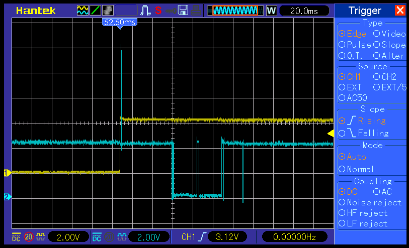
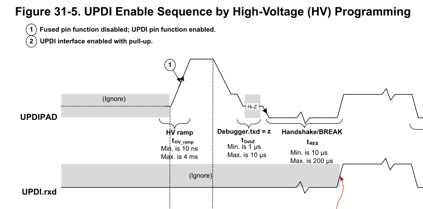
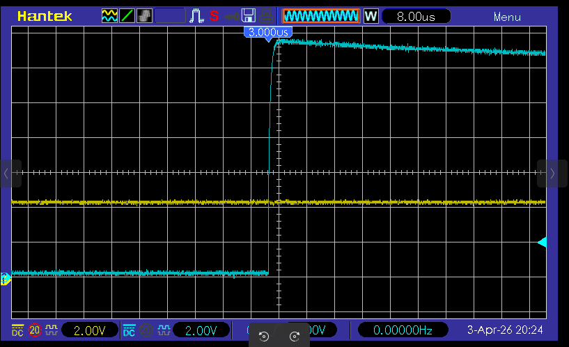
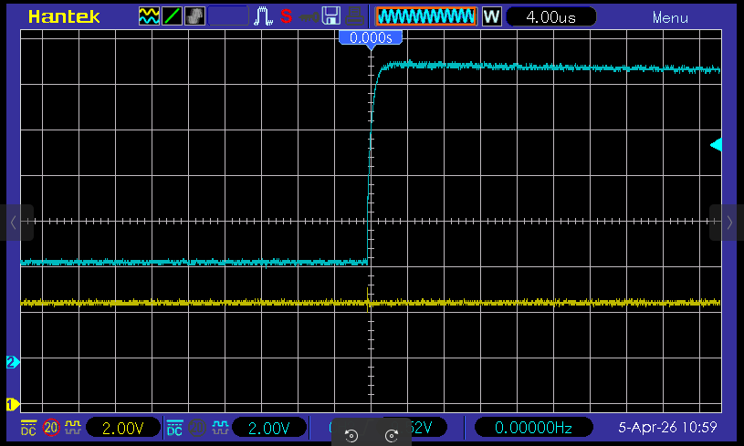
And here is the HV pulse picture…
From a further comment from Hans about the selection of opto coupler in his recommended design, I replaced my 12v boost module with a 23A 12v battery - made no difference.
It’s got to be a timing issue with regard to when exactly adn for how long the 12v pulse is applied to PA0, the UPDI pin.
What am I missing?
Please help me. I am running out of ideas.