I have built a HV UPDI programmer based on work by Technob Tiny UPDI-HV Programmer.
For size and pin count issues, I want to use the UPDI pin for sending serial debug out through the UDPI pin (but re-tasked as GPIO).
This means I have one connection for both programming and seeing debug messages.
I can get it all to work but it’s a bit unstable.
I’ll go through the instability messages etc and finish up with more details about my UPDI programmer.
Before I get started, I’d just like to confirm that without the HV pulse complication, my programmer works great with targets that still have UPDI pin assigned.
My hunch is that my issue is to do with pulse timers but I’d welcome any advice.
OK - story time.
I check I can upload to device (ATtiny402) with programmer set in normal mode (no HV pulse) with UPDI pin still as UPDI.
I can also upload to same device with programmer set to include the HV pulse at start of programming (but no serial debug from UPDI pin - PA0 occurs as I have not changed the fuses yet).
I use Arduino 1.819 with megaTinyCore to ‘burn bootloader’ and set fuse values to set UPDI pin as GPIO pin.
I can upload using programmer with HV set and can (sometimes) successfully upload (and serial debug appears on UPDI pin - PA0).
A digression here. You need to power cycle the device after burning bootloader to change PA0 from UPDI mode - set by HV pulse - back to GPIO mode. Hence my programmer looks for a rise in DTR and after a while uses this to give the target device a power reset.
Back to the story.
Occasionally I get an upload error:
Processing ATtiny402 (platform: atmelmegaavr; board: ATtiny402; framework: arduino)
---------------------------------------------------------------------------------------------------------------------------------------------------------------------------------------------------------------------------------------------------------------------------Verbose mode can be enabled via `-v, --verbose` option
CONFIGURATION: https://docs.platformio.org/page/boards/atmelmegaavr/ATtiny402.html
PLATFORM: Atmel megaAVR (1.6.0) > ATtiny402
HARDWARE: ATTINY402 16MHz, 256B RAM, 4KB Flash
PACKAGES:
 - framework-arduino-megaavr-megatinycore @ 2.5.11
 - tool-avrdude-megaavr @ 3.60300.220118 (6.3.0)
 - toolchain-atmelavr @ 3.70300.220127 (7.3.0)
LDF: Library Dependency Finder -> https://bit.ly/configure-pio-ldf
LDF Modes: Finder ~ chain, Compatibility ~ soft
Found 16 compatible libraries
Scanning dependencies...
Dependency Graph
|-- SendOnlySoftwareSerial
Building in release mode
Checking size .pio\build\ATtiny402\firmware.elf
Advanced Memory Usage is available via "PlatformIO Home > Project Inspect"
RAM:   [==        ]  19.1% (used 49 bytes from 256 bytes)
Flash: [=======   ]  70.1% (used 2873 bytes from 4096 bytes)
Configuring upload protocol...
AVAILABLE: jtag2updi
CURRENT: upload_protocol = jtag2updi
Looking for upload port...
Using manually specified: COM16
Uploading .pio\build\ATtiny402\firmware.hex
Connecting to SerialUPDI
pymcuprog.serialupdi.application - ERROR - SIB read returned invalid characters
pymcuprog.serialupdi.application - WARNING - Unable to read SIB from device; attempting double-break recovery...
Pinging device...
Ping response: 1E9227
Erasing device before writing from hex file...
Writing from hex file...
Writing flash...
pymcuprog.pymcuprog_main - ERROR - Error with st
Done.
*** [upload] Error 1
On trying again I am told the device is in a locked state:
Processing ATtiny402 (platform: atmelmegaavr; board: ATtiny402; framework: arduino)
----------------------------------------------------------------------------------------------------------------------------------------------------------------------------------------------------------------------------------------------------------------------------Verbose mode can be enabled via `-v, --verbose` option
CONFIGURATION: https://docs.platformio.org/page/boards/atmelmegaavr/ATtiny402.html
PLATFORM: Atmel megaAVR (1.6.0) > ATtiny402
HARDWARE: ATTINY402 16MHz, 256B RAM, 4KB Flash
PACKAGES:
 - framework-arduino-megaavr-megatinycore @ 2.5.11
 - tool-avrdude-megaavr @ 3.60300.220118 (6.3.0)
 - toolchain-atmelavr @ 3.70300.220127 (7.3.0)
LDF: Library Dependency Finder -> https://bit.ly/configure-pio-ldf
LDF Modes: Finder ~ chain, Compatibility ~ soft
Found 16 compatible libraries
Scanning dependencies...
Dependency Graph
|-- SendOnlySoftwareSerial
Building in release mode
Checking size .pio\build\ATtiny402\firmware.elf
Advanced Memory Usage is available via "PlatformIO Home > Project Inspect"
RAM:   [==        ]  19.1% (used 49 bytes from 256 bytes)
Flash: [=======   ]  70.1% (used 2873 bytes from 4096 bytes)
Configuring upload protocol...
AVAILABLE: jtag2updi
CURRENT: upload_protocol = jtag2updi
Looking for upload port...
Using manually specified: COM16
Uploading .pio\build\ATtiny402\firmware.hex
Connecting to SerialUPDI
pymcuprog.serialupdi.application - ERROR - Key status = 0x00
The device is in a locked state and is not accessible; a chip erase is required.
Locked AVR UPDI devices can:
 - be unlocked using command: erase --chip-erase-locked-device
 - write user row values using command: write -m user_row --user-row-locked-device
*** [upload] Error 1
But I may need to enter the chip erase command multiple times before it works:
PS D:\Users\Peter\Documents\PlatformIO\Projects\ATtiny402_WalkaboutPowerMonitor> pymcuprog erase --chip-erase-locked-device -t uart -u COM16 -d Attiny402
Connecting to SerialUPDI
pymcuprog.serialupdi.application - ERROR - Key status = 0x00
Pinging device...
pymcuprog.nvm - ERROR - Unable to read signature for detected device in family: 'tinyAVR'
pymcuprog.pymcuprog_main - ERROR - Unable to read device ID
Done.

PS D:\Users\Peter\Documents\PlatformIO\Projects\ATtiny402_WalkaboutPowerMonitor> pymcuprog erase --chip-erase-locked-device -t uart -u COM16 -d Attiny402
Connecting to SerialUPDI
pymcuprog.pymcuprog - ERROR - Operation failed with PymcuprogError: UPDI initialisation failed

PS D:\Users\Peter\Documents\PlatformIO\Projects\ATtiny402_WalkaboutPowerMonitor> pymcuprog erase --chip-erase-locked-device -t uart -u COM16 -d Attiny402
Connecting to SerialUPDI
Pinging device...
Ping response: 1E9227
Chip/Bulk erase:
- Memory type eeprom is conditionally erased (depending upon EESAVE fuse setting)
- Memory type flash is always erased
- Memory type lockbits is always erased
Erased.
Done.
My question is where should I look to improve my set up to make this more stable?
I have tried a selection of devices so I do not believe it to be device specific.
I think it might be a timing thing - for example, how fast do I need to get the HV pulse ‘on’ at onset of programming and DTR drop from serial card - I am putting this through a generic pin debounce routine (albeit set to 0ms timed by millis() but than might be too slow.
I struggle with spec sheets but from the UPDI Enable with 12V Override of RESET Pin section it mentioned using a pulse of 100 μs to 1 ms I measured my pulse at 127us.
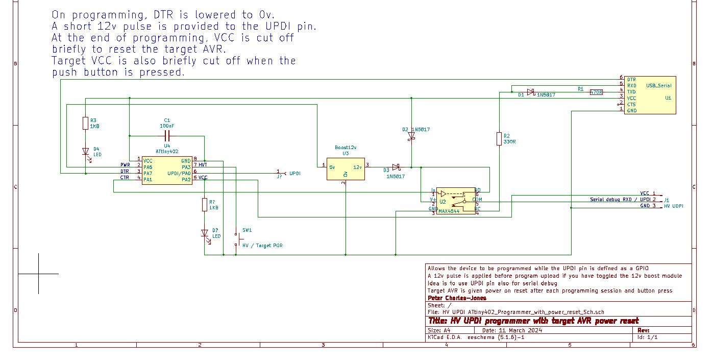
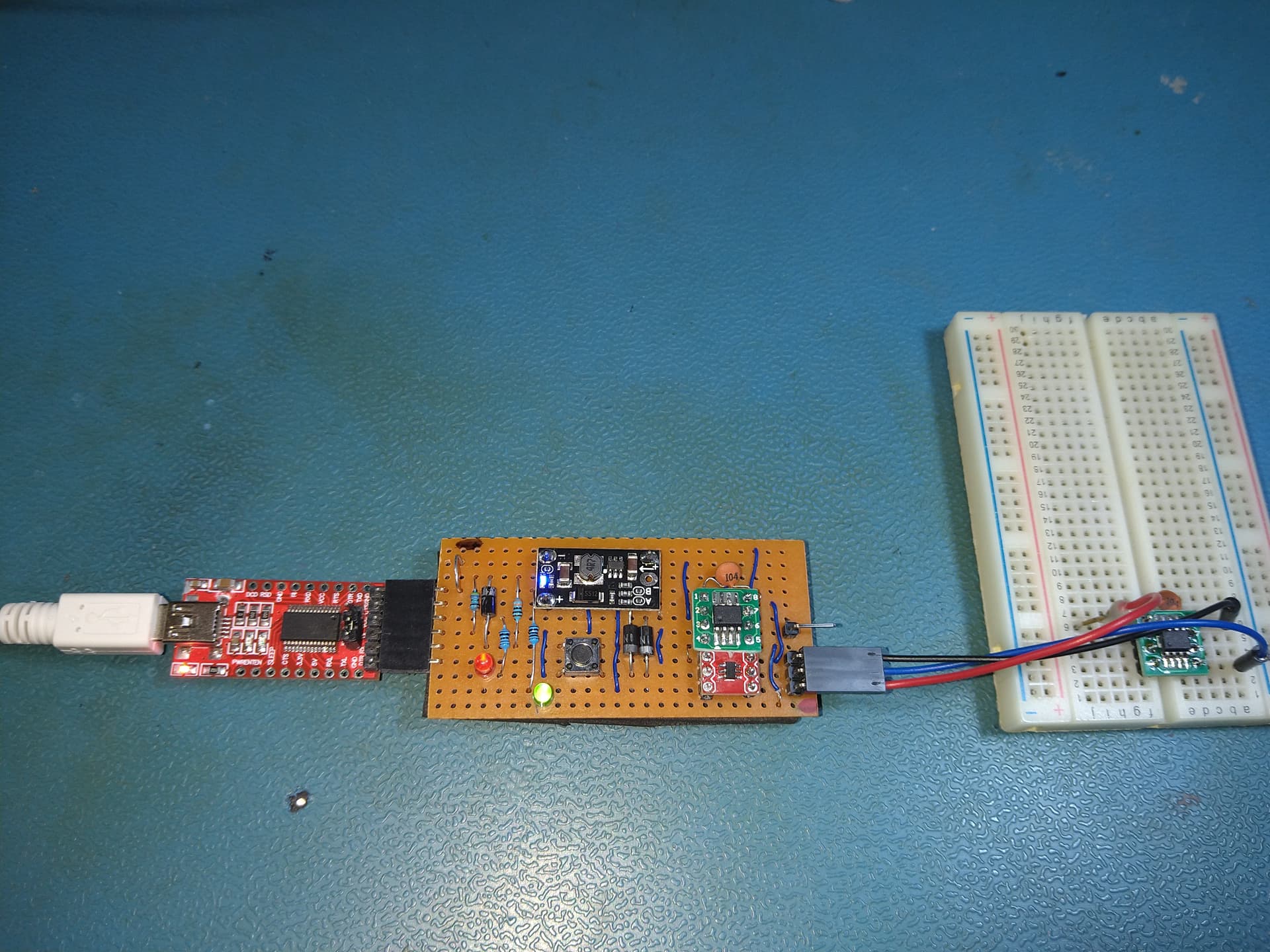
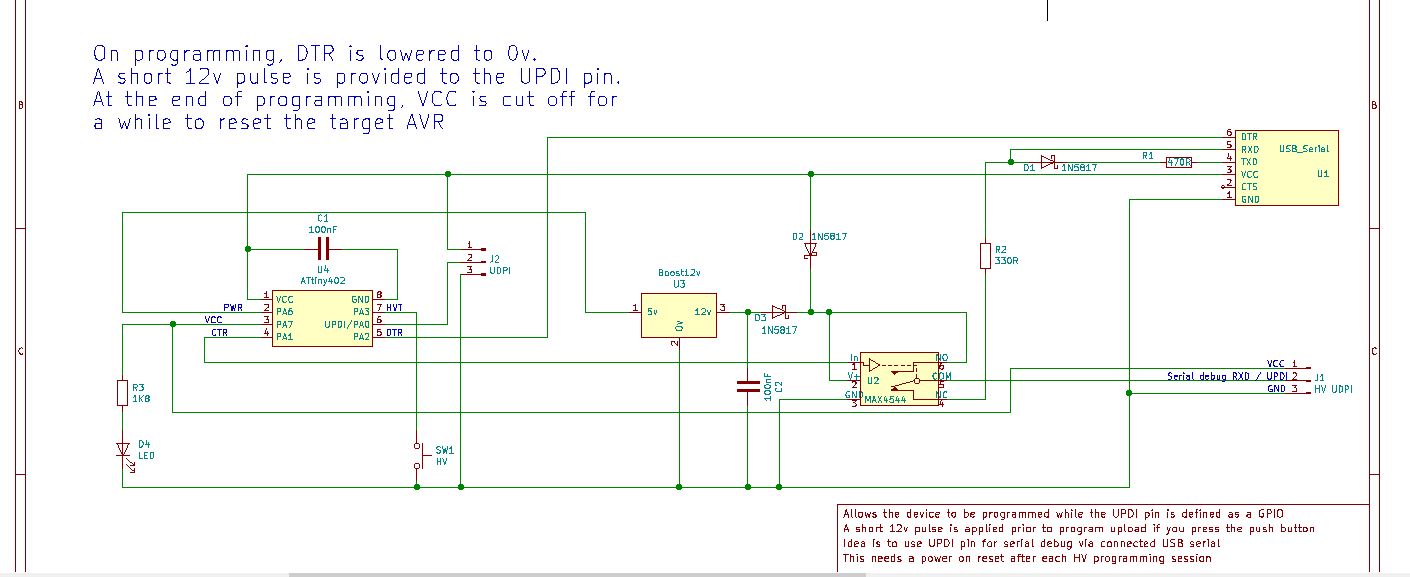
Here’s my circuit:
Here’s the code in the AVR that monitors DTR and controls the HV pulse.
// ATtiny402_HV_UPDI
// Peter Charles-Jones

// Code Spell Checker Visual Studio extension - provides spell checking for comments
// cSpell:includeRegExp CStyleComment

/* The Environment
This  was designed using PlatformIO (free) which is an extension of Visual Studio (free)
The big advantage to Arduino 1.8.19 (free) is the intellisense editor which can suggest register names, highlight scope errors, rename variables and so on
Atmel's Studio 7 (free) is worth a mention as it provides a basic set of peripheral setup code via its AtmelSTART projects
It also has a really good GUI fuse editor for older style MCUs eg ATtiny85, Atmega328 etc
*/

/* What is the device
See the data sheet here <https://ww1.microchip.com/downloads/en/DeviceDoc/ATtiny202-402-AVR-MCU-with-Core-Independent-Peripherals_and-picoPower-40001969A.pdf>
Series '0' and '1' devices use Universal Programming Debug Interface (UPDI) which uses 1 pin interface plus ground and positive.
Typically you need to build your own UPDI programmer by modifying a standard serial interface module - see the links below.
If you want to use the UPDI pin as a standard GPIO pin, you need to follow the instructions at <http://www.technoblogy.com/show?48MP>
to create a High Voltage (12v) programmer.
If you do this - suggest you use the UPDI pin as push button input or as debug serial output where either the programmer or serial monitor
are connected (but not both at the same time).
*/

/* General approach to UPDI
	I purchased an original ATtiny402 direct from Microchip - the exact part code was ATTINY402-SSN.
	This part was available as it's not automotive spec and comes in a tube so there was no part reel cutting fee.
	Beware buying devices from generic suppliers such as eBay, AliExpress - I purchased devices with duff device ID (and pin multiplex table issues)

	The upload command used pymcuprog which had to be installed within PlatformIO terminal break out rather than directly on PC.

	The ATtiny402 was programmed using a UPDI programmer made from a UTP to serial device with a diode between TXD and RXD.

	--------------------    	                          To Target device
		           	DTR|	                  330 ohm     __________________
		internal    Rx |--------------,--------\/\/------| UPDI------------->
	  Tx---/\/\/\---Tx |-------|<|---'          .--------| Gnd
	   	resistor    Vcc|---------------------------------| Vcc
	    typ 1-2k    CTS|                     .`          |__________________
	       			Gnd|--------------------'             If you make a 3-pin connector, use this pinout
	--------------------

	Here's a bunch of links that describe this in more detail....
	<https://github.com/SpenceKonde/AVR-Guidance/blob/master/UPDI/jtag2updi.md>
	<https://pypi.org/project/pymcuprog/>
	<https://github.com/SpenceKonde/megaTinyCore/blob/master/megaavr/extras/PlatformIO.md>
	<https://docs.platformio.org/en/latest/platforms/atmelmegaavr.html#upload-using-pymcuprog-serialupdi>
	<https://community.platformio.org/t/problems-migrating-from-studio-7-to-platformio-attiny402-with-pymcuprog-custom-tool/29352/9>

	I used Studio START code generator to get used to the peripheral configuration code
	I put all the initial set up required in a system_init() routine and put this code at the bottom
	below the main() loop structure.

	Direct Port Manipulation - Warning

	See what Spence Konde (AKA Dr Azzy) has to say about direct port manipulation
	<https://github.com/SpenceKonde/megaTinyCore/blob/master/megaavr/extras/Ref_DirectPortManipulation.md>

	Interrupts and flag setting
	The setting of multiple FLAG bits is not atomic (may be interrupted by an interrupt service routine) and if an interrupt sets a bit during such an update eg
	FLAG &= ~((1<<night_set_bp)|(1<<detection_set_bp));
	the bit set by the interrupt would be lost - so we need a separate set of interrupt flags - hence INT_FLAG and this must be defined as volatile

*/
/* Pin Multiplexing summary
pin Pin Name  Other/Special ADC0 AC0  USART0  SPI0  TWI0  TCA0  TCB0  CCL
6   PA0       ~RESET/UPDI   AIN0      XDIR    ~SS                     LUT0-IN0
5   PA1                     AIN1      *TXD    MOSI  SDA   WO1         LUT0-IN1
4   PA2       EVOUT0        AIN2      *RxD    MISO  SCL   WO2         LUT0-IN2
7   PA3       EXTCLK        AIN3 OUT  XCK     SCK         WO0/WO3
8   GND
1   VDD
2   PA6                     AIN6 AINN0 TXD    *MOSI             WO    LUT0-OUT
3   PA7                     AIN7 AINP0 RXD    *MISO       *WO0        LUT1-OUT

Note * indicates alternate pin

TCA0 is the default timer used for millis() and Delay() in the Arduino wrapper.

When designing a thing, you will be constrained by what your MCU pin multiplex table can support.
Best start with the basics to see if what you are trying to do will fit your MCU
*/
/* Pin information
			    ATtiny402
			     ---u---
    	  	VDD|	    |GND
   	 	PWR PA6|	    |PA3 HVT
  		TVC PA7|	    |PA0
	  	CTR PA1|		|PA2 DTR
    			 -------
*/
/* isues
 If you corrupt the lock bits (with UDPI pin as GPIO) and PlatformIO says you need to do a chip erase - you may just re-burn the boot loader from Arduino IDE
 Or you could try the chip erase command from the terminal:

 pymcuprog erase --chip-erase-locked-device -t uart -u COM16 -d Attiny402

 Currently this aspect of the HV UPDI is a bit flakey and unstable - looking for improvements
*/

// put pre-compile code here:
#define F_CPU 16000000L		// this tells the code the clock is running at 16MHz (it does not define how fast the clock is running)- see CLKCTRL_init()

// the include code tells the compiler to use code in these libraries - generally this makes coding easier
#include <Arduino.h>        // so we can use the Arduino framework - thanks Dr Azzy!

// the define statements tell the compiler to replace the first element with the second
// Define names for the pins for easy reference
#define PWR_bp 6 // PA6 output Power for boost 12v (so you get a built in 'POWER ON' LED on the module)
#define VCC_bp 7 // PA7 output VCC for target so you can control a target power reset
#define CTR_bp 1 // PA1 output to control switch to actually switch in teh HV pulse into the UPDI connector
#define HVT_bp 3 // PA3 input HV toggle button - starts off in normal mode (not HV) - an LED hung on VCC_bp pin indicates the power reset
#define DTR_bp 2 // PA2 input DTR detector - hoosk into DTR of serial to USB adapter

#define button_debounce 50				// button debounce (ms)
#define DTR_debounce 0					// signal debounce (ms)- don't  want to delay application of HV pulse when DRT drops and it won't need debouncing
#define HV_pusle_time_max 100			// HV pulse duration (us) [actually measured pulse at CTR / PA1 of 126us]
#define post_prog_delay_time_max 8000 	// delay after DRT raise before power reset to target AVR (ms) The timer is reset while FLAG: Prog_bp is set
#define reset_time_max 2000				// power down period for target AVR after post prog delay (ms)

// bit definitions for FLAG - an 8 bit byte, each bit is used to flag status info to the main code
#define HV_On_bp 0 						// FLAG :HV powered up
#define PROG_bp 1						// FLAG: UPDI programming in progress
#define HV_PULSE_bp 2					// FLAG: HV pulse is in progress
#define Pause_Pulse_bp 3				// FLAG: Post programming pause is in progress
#define Reset_Pulse_bp 4				// FLAG: Target AVR VCC has been set to GND


// variables used by setup() and loop() - these functions are specific to Arduino.

// global variable declaration
uint8_t tempPINA = VPORTA_IN;                  							// used as snapshot for PINA status if it changes mid process
uint8_t pinAHistory = VPORTA_IN;                       					// the last read PINA status
uint8_t debounced_PINA = VPORTA_IN;										// debounced copy of the PINA register
uint8_t FLAG;															// flags for program control - see above bit definitions

unsigned long last_HVT_time = millis();                					// debounce timer (ms)
unsigned long last_DTR_time = millis();                					// debounce timer (ms)
unsigned long HV_pulse_time = micros();									// HV pulse timer (us)
unsigned long post_prog_delay_time = millis();							// post programming delay timer (ms)- to give you time to open up the terminal before teh target AVR is power cycled
unsigned long reset_time = millis();									// target AVR power off pulse timer (ms)

// put function declarations here: - a 'place holder' allowing the complier to reference functions before they have been fully defined.
int pinChange (unsigned long* last_time, int pinID, int debounce);		// has pin changed?
int pinHIGH (int pinID);												// is pin HIGH?
void system_init();   													// initializes the peripherals

void setup() {
  	// put your setup code here, to run once:
	system_init();														// initialize peripherals
}

void loop() {
	// put your main code here, to run repeatedly:

	// check the pins for any changes
	tempPINA = VPORTA_IN;                             					// get a snapshot of current PIN setting

	// Check HVT for a key press
	if (pinChange(&last_HVT_time, HVT_bp, button_debounce)){
		if (!(pinHIGH(HVT_bp))){               							// HVT is LOW - CC - button pressed
			if(!(FLAG & (1<<HV_On_bp))){
				FLAG |= (1<<HV_On_bp);
				VPORTA_OUT |= (1<<PWR_bp);								// power up the 12v boost board
			}
			else {
				FLAG &= ~(1<<HV_On_bp);
				VPORTA_OUT &= ~(1<<PWR_bp);								// power down the 12v boost board
			}
    	}
	}

// Check DTR for a key press
	if (pinChange(&last_DTR_time, DTR_bp, DTR_debounce)){
		if (!(pinHIGH(DTR_bp))){               							// DTR is LOW - CC - UPDI programming in progress
			if(!(FLAG & (1<<PROG_bp))){
				FLAG |= (1<<PROG_bp);									// flag that programming has started
				if (FLAG & (1<<HV_On_bp)){								// HV programming so send HV pulse
					HV_pulse_time = micros();							// start HV pulse
					VPORTA_OUT |= (1<<CTR_bp);							// switch the 12v onto UDPI output
					FLAG |= (1<<HV_PULSE_bp);							// set the flag
				}
    		}
		}
		else{															// DTR has gone HIGH - UDPI programming is over
			if (FLAG & (1<<PROG_bp)){									// programming was in progress
				post_prog_delay_time = millis();						// reset the delay timer - can happen multiple times if programmer can't establish UDPI link with target AVR
				FLAG |= (1<<Pause_Pulse_bp);
			}
		}
	}
	pinAHistory = tempPINA; 											// update the PINA history with the latest snapshot of PINA

	if (FLAG & (1<<HV_PULSE_bp)){										// if an HV pulse is in progress
		if ((micros() - HV_pulse_time) >= HV_pusle_time_max){			// time to end the HV pulse (allowed value range 10ns to 4ms - we have 127us)
			FLAG &= ~(1<<HV_PULSE_bp);									// clear the flag
			VPORTA_OUT &= ~(1<<CTR_bp);									// switch 12 v out
		}
	}

	if (FLAG & (1<<Pause_Pulse_bp)){										// if an delay pulse is in progress
		if ((millis() - post_prog_delay_time) >= post_prog_delay_time_max){	// time to end
			FLAG &= ~(1<<Pause_Pulse_bp);									// clear the flag
			reset_time = millis();											// reset reset timer
			FLAG |= (1<<Reset_Pulse_bp);									// set reset in progress flag
			VPORTA_OUT &= ~(1<<VCC_bp);										// drop power to target AVR
			FLAG &= ~(1<<PROG_bp);											// clear PROG flag at the end of the pause to allow timer to be restarted multiple times if DTR goes up and down
		}
	}

	if (FLAG & (1<<Reset_Pulse_bp)){										// if an delay pulse is in progress
		if ((millis() - reset_time) >= reset_time_max){						// time to end
			FLAG &= ~(1<<Reset_Pulse_bp);									// clear the flag
			VPORTA_OUT |= (1<<VCC_bp);										// power restored to target AVR
		}
	}
}

// put function definitions here:

int pinChange (unsigned long* last_time, int pinID, int debounce){ 		// has the pin changed state?
	if ((tempPINA & (1<<pinID))!= (pinAHistory & (1<<pinID) )){			// last pin state different
    	*last_time = millis();
  	}
	if ((millis() - *last_time) > debounce){							// debounce time has elapsed
		if ((tempPINA & (1<<pinID))!=(debounced_PINA & (1<<pinID))){	// is the current pin state different from the current one
			debounced_PINA &= ~(1<<pinID);								// mask out the bit position
			debounced_PINA |= (tempPINA & (1<<pinID));					// get the bit value at bit location and OR into PINS
    		return 1;													// pin has changed
    	}
  	}
	return 0;                                                 			// pin has not changed state
}

int pinHIGH (int pinID){												// is the pin HIGH?
	if (debounced_PINA & (1<<pinID)){                                  	// pin value is 1.. switch / button is Open Circuit
    	return 1;                                             			// HIGH
  	}
	else{                                                     			// pin value is 0 .. switch / button is Closed Circuit to ground
    	return 0;                                             			//LOW
	}
}

// Interrupt Service Routines

/*	Helper routines - to make the code more readable */
void disablePortAPullup(uint8_t pin){											// code only does this to ADC pin and this has no interrupt so ignore the ISC code
	uint8_t *port_pin_ctrl = ((uint8_t *)&PORTA + 0x10 + pin);					// calculate port PINCTRL address for pin
	*port_pin_ctrl &= ~(1 << PORT_PULLUPEN_bp);									// disable pull up

}

// initialization functions:
void mcu_init()							// MCU initialization
{
	// On AVR devices all peripherals are enable from power on reset, this
	// disables all peripherals to save power. Driver shall enable
	// peripheral if used

	// Set all pins to low power mode with pull up resistor enabled
	for (uint8_t i = 0; i < 8; i++) {
		*((uint8_t *)&PORTA + 0x10 + i) |= 1 << PORT_PULLUPEN_bp;
	}
}

void pin_init(){ 						// PIN initialization
	VPORTA.DIR |= (1<<PWR_bp);			// set pin as output
	disablePortAPullup(PWR_bp);         // disable pull up resistor

	VPORTA.DIR |= (1<<VCC_bp);			// set pin as output
	disablePortAPullup(VCC_bp);         // disable pull up resistor
	VPORTA_OUT |= (1<<VCC_bp);			// set power on for AVR target

	VPORTA.DIR |= (1<<CTR_bp);			// set pin as output
	disablePortAPullup(CTR_bp);         // disable pull up resistor
}

void system_init(){						// system initialization
	mcu_init();
	pin_init();
}
And lastly the PlatformIO.ini for this :
; PlatformIO Project Configuration File
;
;   Build options: build flags, source filter
;   Upload options: custom upload port, speed and extra flags
;   Library options: dependencies, extra library storages
;   Advanced options: extra scripting
;
; Please visit documentation for the other options and examples
; https://docs.platformio.org/page/projectconf.html

[env:ATtiny402]
platform = atmelmegaavr
board = ATtiny402
framework = arduino
upload_speed = 115200
upload_port = COM12
upload_flags =
    --tool
    uart
    --device
    attiny402
    --uart
    $UPLOAD_PORT
    --clk
    $UPLOAD_SPEED
upload_command = pymcuprog write --erase $UPLOAD_FLAGS --filename $SOURCE
I worried that the Schottky diode in line with 12v (required to stop 5v otherwise still illuminating LED on boost module.) would take too much off the 12v but I tried without the Schottky diode with the full 12v and it made no difference.
I originally tried the circuit with an RC network on DTR to force a reset when DTR rises after programming but having an AVR do this makes for more control options.
Another hunch I am going to explore is forcing a target device power on just before applying the 12v in response to this from the spec sheet “It is recommended to always reset the device before starting the 12V enable sequence.”
I may extend the HV pulse to be more mid range between 100us and 1ms. (This seems to differ from the Technobology write up).
If you have any suggestions as to what to look at next, I’d welcome the input.
Many thanks