Hey,
I don’t know how to use my arduino mega2560 as a programmer. I want to programm a atmel 644 via isp with my arduino.
Actually I did the following steps
Open arduino ide and flash the arduino with the example programm arduino isp
Open VSCode and platformio and select my atmel 644 for the project.
Connecting arduino and 644 via isp.
Now I want to upload a simple blinky programm. Led is connected to pin 5.
But I don’t get any response. The terminals response is that the get_synck() 1 of 10.
Can I programm the ardunio as programmer via the platformio and flash the atmel644 by one platform.ini ? When yes how should my platform.ini should look like ? Or have to do it in two steps and different projects ? Thanks for help and for a detailed instructions i would be great full
My platform.ini looks like a normal ini ehen you generate a new project for atmega644.
Wirering is via a isp wire. So i use the isp chanel over the 2 big port lines at the mega and connect it to an isp that is connected to the 644.
My major problem is I don’t even know how to flash my arduino that it is a programmer via isp for my 644. What are the first steps how should my initial look like. Have to start with an ini that my arduino knows he is a programmer. Or I only have to use a ini like that one :
[env:megaatmega2560] platform = atmelavr framework = arduino board = megaatmega2560 upload_protocol = arduinoisp
And when yes what option in vscode i have to choose uploading or uploading with programmer ?
where you must replace SERIAL_PORT_HERE with the serial port that your Arduino Mega “Arduino as ISP” device is connected to, e.g. COM4.
To PlatformIO it doesn’t matter whether you flash an Arduino Mega or Arduino Uno or Arduino whatever with the Arduino as ISP firmware (you also don’t reference a “Arduino Mega” in the platformio.ini), it just has the commands to interact with a STK500V1 style programmer that is implemented by the board when it’s running the Arduino as ISP sketch.
Thanks i would try your ini. I use the normal atmega 644 without any p or a behind.
So first i have to upload the arduinoisp sketch at arduino ide. Then go to vscode and copy your ini with some differences in my ini and then flash it via upload with programmer or normal upload ?
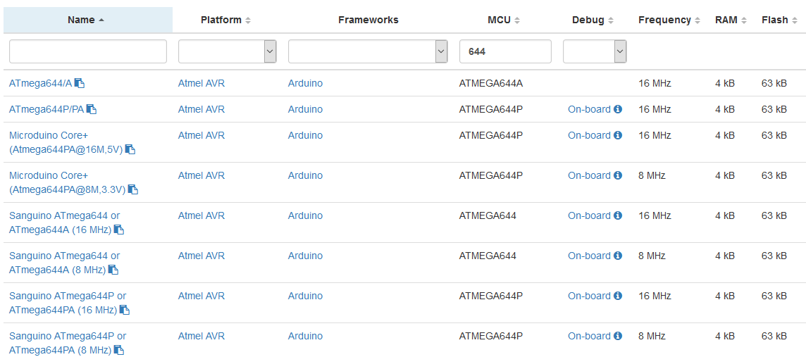
Mature product; not recommended for new designs. Replaced by ATmega644PA.
Please try the above platformio.ini anyways.
If the chip turns out to be wrong, please change the config to board = sanguino_atmega644_8m from docs, “Sanguino ATmega644 or ATmega644A (8 MHz)”. It’s an 8MHz configuration for the ATMega644.
(Previous state of the post with a custom board JSON file was not needed: PlatformIO already knows about such a pure ATMega644 config)
Correct. Upload or upload with programmer shouldn’t make a difference, try normal upload first. As the project’s source code either try empty loop and setup or directly some blinky code if you have the hardware for it.
Just as an additional sanity check, did you build your own board or have the raw chip on breadboard / breakout board and you want to program it? Or are you using a premade board that might already be supported directly and has a different chip after all?
Hello, I’m working with @miros.407 on the project. I tried to use the ini file @maxgerhardt posted. My Serial Port is COM5 and I replaced the SERIAL_PORT_HERE with COM5.
Now I’m getting the Error Code:
avrdude: can’t open config file “C:\Users\HP”: Permission denied
avrdude: error reading system wide configuration file “C:\Users\HP”
*** [upload] Error 1
Any ideas on how to give the permission?
I have found the path: -C
C:\Program Files (x86)\Arduino\hardware\tools\avr\etc
is read-only.
In the platformio.ini, can you replace $PROJECT_PACKAGES_DIR/tool-avrdude/avrdude.conf with "$PROJECT_PACKAGES_DIR/tool-avrdude/avrdude.conf" please (quoting should escape the path properly)
avrdude: Device signature = 0x000000
avrdude: Yikes! Invalid device signature.
Double check connections and try again, or use -F to override
this check.
avrdude done. Thank you.
*** [upload] Error 1
================================================================================================== [FAILED] Took 2.09 seconds ==================================================================================================
The terminal process “C:\Users\HP Gaming Rechner.platformio\penv\Scripts\pio.exe ‘run’, ‘–target’, ‘upload’” terminated with exit code: 1.
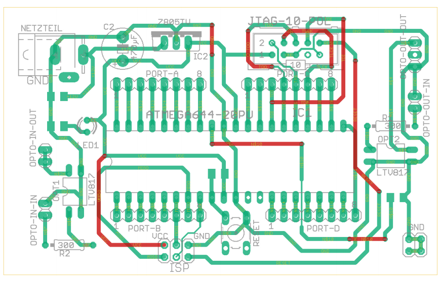
The picture is cutoff at the left so I can’t see if you have a capacitor installed between RST and VCC, further the breadboard at the bottom is cut off.
A thing I find weird in the target board is the RESET line. Am I blind or does the bottom right pin of the ISP header, which is supposed to be RESET, go nowhere, just between the two headers themselves, but not to the actual RESET pin of the chip, which is just connected to one pin of the button? Hardware error? The SPI SlaveSelect (SS) line must definitely go the RESET of the target.
You can check whether it makes a difference if you connect the the SS pin of the Mega to the bottem left pin of the reset button (in regards to the above posted picture) (or touch it while programming with a male-male cable). The RESET button is an input connected to nothing else (if you don’t press the button) so nothing bad should happen.
Edit: Also, the page https://www.arduino.cc/en/Tutorial/BuiltInExamples/ArduinoISP should be the main source of information for the wireup. There are different wireups in there, e.g. RESET <-> RESET or SS <–>RESET with caps and not. Just glossed over it, maybe you can extract some more information from this and try a few different things.
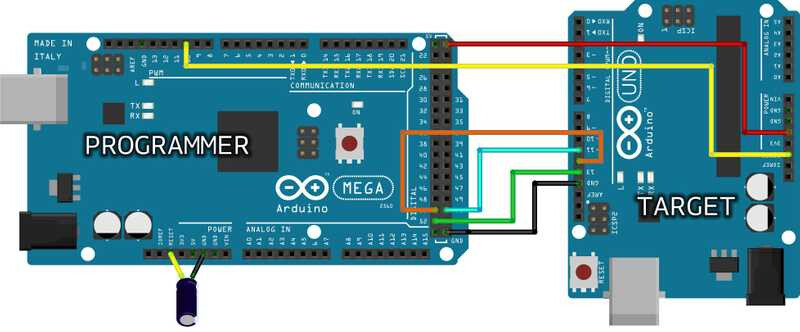
This is the suggested wiring for using a Mega as a ISP programmer… although it’s for a Uno, same principle applies, and you can read between the lines as to which pins on the target match the 644
The Arduino MEGA above is programming an Arduino UNO connecting D51-D11, D50-D12, D52-D13, GND-GND, 5V-5V and D10 to RESET. This type of board needs a 10µF electrolytic capacitor connected to RESET and GND with the positive (long leg) connected to RESET. The capacitor has to be placed after the programmer board has been loaded with the ISP sketch.
The 10µF electrolytic capacitor connected to RESET and GND of the programming board is needed only for the boards that have an interface between the microcontroller and the computer’s USB, like Mega, Uno, Mini, Nano. Boards like Leonardo, Esplora and Micro, with the USB directly managed by the microcontroller, don’t need the capacitor.
Basically, if you don’t put it on the Mega after loading the ArduinoISP sketch, your Mega will reset instead of the target board, which isn’t very helpful! Or at least, that’s what I think it prevents!
Looks like the 644 RST should be connected to D10 on the Mega, not SS…
Longer answer: Yes absolutely because the capacitor suppresses a voltage drop of the RESET line from high to low when programmer tool initializes the device and does an eventual auto-reset, like @pfeerick said.
Some thoughts of mine:
double check with a multimeter that the reset pin of the ISP header goes through to the actual reset pin of the ATMega644. If it’s not, then the programmer can impossibly reset the chip, and then you need to make direct connection to that pins, somehow, either by soldering it or tapping that pin with the needed wire
double check that you’re NOT feeding 5V from the Arduino Mega into the target board when the target board is connected to its power supply at the same time! You’ll have two power supplies fighting each other and there’ll be a current between them. Either disconnect VCC between the two boards or disconnect the power supply from the target board (5V from the Mega should be plenty to power your target board which only has like the MCU and 3 other chips…)
double check voltages on the board to see if between GND and VCC of the board there really is a good 5V supply
note that I’ve seen that the ISP sketches / resources talk about “old school wiring” and new wiring. So there might be conflicting information around. Look into the source code of the exact (and hopefully recent) version of the Arduino as ISP sketch that you’re putting on your Arduino Mega, it should already tell you exactly how the wireup is supposed to be
you can sanity check that the “Arduino as ISP” Mega board is generally working by e.g. flashing a known-good Arduino Uno with the exact wireup as shown above. This would instantly eliminate the programmer from being the problem
if you’ve tried all wiring methods, all the voltages seem good and the programmer works in general on another chip then you can
Add -F on a new line in the list of upload_flags of the platformio.ini, to try a “force”
If this very likely makes no difference replace the ATMega644 of your target board, as it might by truely dead by “something”. From your pictures I do see that the chip is socketed so you can just pull it out and put a new one in, if you have a replacement part (that can also still be ordered today)
as another caveat: your microcontroller has no crystall oscillator attached to its XTAL1 and XTAL2 pins, it’s just an empty hole. The microcontroller should recognize that and start up on its internal RC oscillator (8MHz) though, I hope. Otherwise the chip will just do nothing without a clock. Possible clock settings are listed in the core