I may need to clock my ATtiny84 with an external 8MHz crystal so it’s nice and stable for data reception.
I realise I need to blow fuses to achieve this and that once done, there is no going back (without a VH programmer).
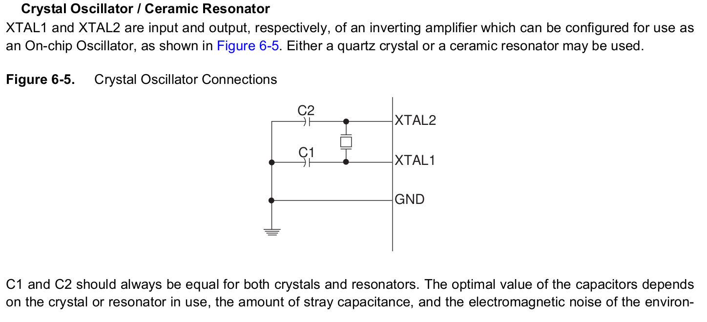
My query is - how do I declare the pins in question? XTAL1 is PB0 and XTAL2 is PB1 - should these be declared as digital input? - do I enable the pull up resistor? Or is one a digital output?
Or should I just not declare them as anything? - this is my hunch as there was talk of amplifiers and the C to ground on each pin don’t seem ‘digital’.
I’ve had a look in the data sheet but could not find what I would call a definitive answer.
I am keen to get this right first time as I only have a few ATtiny84s to play with.