Help with I2C for STM32 and mbed

Hi,
I am pretty lost with my new objective of working with stm32’s and mbed OS… I have tried directly sending commands to a 2x16 LCD with a PCF8574 I2C expander, but no luck and I cannot understand why… refering to the Liquidcrystal_LCD library, sending a 0x01 command should turn on the back light, and 0x00 should turn it off… Am I missing something? From the I2C mbed doc, everything should be fine. I tried setting my frequency to 100kHz and it didnt work either!! If it wasnt for quarantine, it would have been a complete waste of friday night!

#include <mbed.h>

/*
LCD with PCF8574 i2c expander (0x27 default adr) & PCF8574A (0x3F default adr)
Communication Mode	I2C(100Kbit/s)

*/

#define I2C_F (100000) //100kHz I2C
// mbed libs use the 8bit format for I2C addresses
// leftshift the 7bit address by one bitposition to get the 8bit address.
#define LCD_ADR (0x3F << 1)

int main()
{

  I2C i2c_lcd(PB_11, PB_10);
  DigitalOut led_in(LED2);
  Serial pc(USBTX, USBRX);

  char offCmd[1] = {0x00};
  char onCmd[1] = {0x01};

  while (1)
  {

    i2c_lcd.write(LCD_ADR, onCmd, 1);
    thread_sleep_for(500);

    i2c_lcd.write(LCD_ADR, offCmd, 1);
    thread_sleep_for(500);

    led_in = !led_in;
    pc.printf("led is %d\n\r", led_in.read());
  }
}

According to the datasheet that writes 0x00 to the output ports P7…P0 and the later only turns on P0. Is the backlight connected to P0 of the I2C expander?

Your I2C code looks fine to me. Now of course the address of the chip can be wrong if it is configured differently in hardware.

grafik

Can you run the following I2C scanner sketch to see if the address is right?

#include <mbed.h>

I2C i2c(PB_11, PB_10); // SDA pin, SCL pin
Serial pc(USBTX, USBRX); // TX pin, RX pin

int main()
{
	pc.baud(115200);
	wait_ms(2000);
	pc.printf("Hello World!\n");

	int count = 0;
	for (int address = 0; address < 127; address++)
	{
		if (!i2c.write(address << 1, NULL, 0)) // 0 returned is ok
		{																								  
			pc.printf("I2C device found at address 0x%02X (0x%02X in 8-bit)\n", address, address << 1);
			count++;
		}
		wait_ms(20);
	}
	if (count)
		pc.printf("%d", count);
	else
		pc.printf("No");
	pc.printf(" device found\n\n");
}

Other causes could of course be a wrong hardware connection, which I can’t judge if I don’t know what pin you connected to what pin exactly and what your target microcontroller is. For the STM32F051R8, it has indeed an I2C peripheral on

But the question is whether you’re also connecting it to those pins, and what other connections are made to the I2C LCD.

Hi Max,
the I2C scanner code was very helpful, thank you.

It has let me notice that my I2C wasnt even working, I replaced the pins for PF_0 and PF_1 and it works. As you mentioned, the 0x01 only turns on P0 and it is observably not connected to the backlight, because now my code turns the backlight off and never turns it on again.

But how did you get the 0x00 command exact effect from the datasheet? I looked and I cannot seem to find any section in the doc that would help me know which commands to send to turn on the blacklight!!

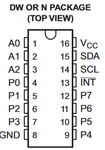
The datasheet (https://www.ti.com/lit/ds/symlink/pcf8574.pdf) first shows the package pinout (in one of 4 different versions)

grafik

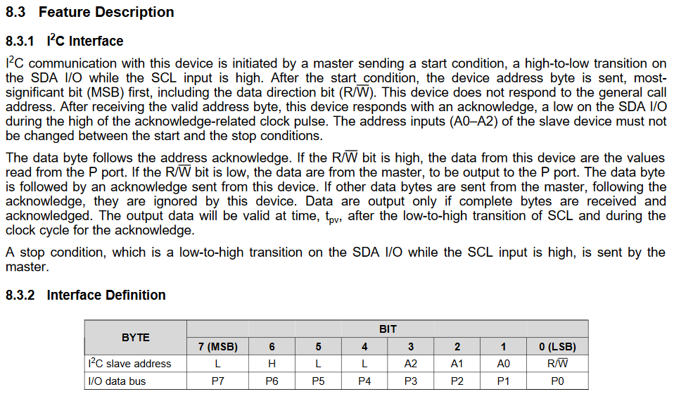
And then in chapter 8.3 and 8.4, it shows how an I2C write operation is used to set the values of the output pins P7…P0.

In other words, doing an I2C write operation on the devices’s address followed by one byte (8 bits) will set the 8 output pins P7…P0 to that sent one byte. That can also be seen in Arduino library code.

So now that PCF8574 expander’s data bus (P7…P0) is in some way connected the LCD screen.

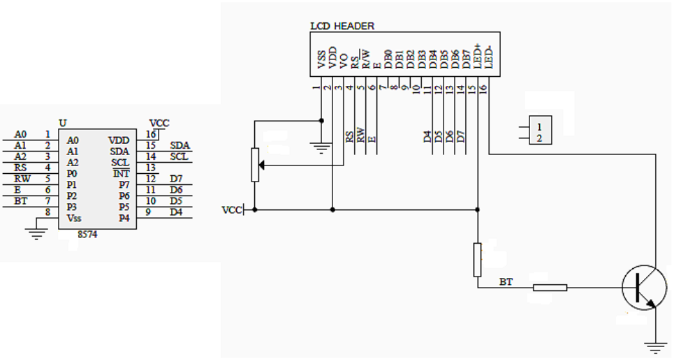
I’m taking this module as an example of how it’s connected to an LCD now.

As you can see in this reference diagram (that they say is the intended usage of the module), the LED+ of the LCD is conncted to VCC (+5V/+3.3V). The backlight is turned on when current flows from LED+ through LED-, so, LED- has to be put to GND. The LED- can be switched to GND via the BJT NPN transistor, whose base pin is connected to the “BT” pin, which is in turn “P3” of the I2C expander. So with these connections between the expander and the backlight it is clear that we need to send set P3 to “1” / HIGH to activate the transistor to turn on the backlight and “0” respectively to turn it off.

Thus in that configuration we would need the on/off commands to be

  uint8_t offCmd[1] = {0x00};
  uint8_t onCmd[1] = {(uint8_t)(1 << 3)}; /* for P3. equivalent 0x08 */

(I’ve taken the liberty to correct the types to unsigned 8-bit).

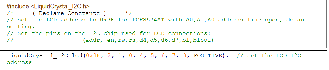
This pin mapping is further confirmed in the PDF by the given Arduino example code. The constructor to the LiquidCrystal_I2C object gives the pin mapping from the I2C expander to the LCD pins.

And there you can see again that P3 maps to the backlight, and has polarity “POSITIVE”, aka a HIGH on P3 will make it turn on.


You can also begin to see a thing with mbed-os: Libraries are a bit few and sparse and vary in code quality, especially user code from https://os.mbed.com/ – often times pins are just hardcoded, e.g…

In this case however there are libraries available. In fact, a port of LiquidCrystal_I2C, to be exact: PlatformIO Registry (with mbed-os example: LiquidCrystalIO/examples/helloMbed/helloMbed.cpp at master · davetcc/LiquidCrystalIO · GitHub). In this case howeever, the library and its dependencies are so big that it does not compile for disco_f051r8 – by 504 bytes in RAM usage. I’ve uploaded that reference project for the above board and for the larger chip on the Nucleo L476RG here: GitHub - maxgerhardt/pio-mbed-i2c-lcd-example: An PlatformIO compilable example for mbed-os and an LCD display connected to an I2C expander.

Thus another lesson with mbed-os is: most cases, compiling for mbed-os takes more Flash and RAM than Arduino. And that’s bad for small microcontrollers.

Another library might be small enough to fit: LiquidCrystal_I2C - Port of the Arduino library with the same library… | Mbed. That is compilable: GitHub - maxgerhardt/pio-mbed-i2c-lcd-example-f051: PlatformIO compilable example for the disco_f051r8 board and I2C LCD display

But gets the chip to its limits.

Checking size .pio\build\disco_f051r8\firmware.elf
Advanced Memory Usage is available via "PlatformIO Home > Project Inspect"
RAM:   [====      ]  43.8% (used 3592 bytes from 8192 bytes)
Flash: [========= ]  92.9% (used 60868 bytes from 65536 bytes)

Size constraints are a major caveat with mbed-os… Looking back I should have looked at your chip more closely and said that with 64KByte flash and 8Kbyte of RAM, mbed-os will run into limitations extremely fast – maybe an addition to the Arduino core will be much better, if done correctly :slight_smile:

Hi Max,
thank you so much for this clear response. I

So with these connections between the expander and the backlight it is clear that we need to send set P3 to “1” / HIGH to activate the transistor to turn on the backlight and “0” respectively to turn it off.

This command will be very easy to implement now that you explained it. I didnt check the LCD’s data sheet yet, but you think you could estimate the amount of hours I will have to put in in order to develop a code interface to let me do basic stuff like writing characters? I dont want to redevelop the whole library, just enough to get me going. I am also interested in the st7789 tft screen, which seems hard to setup without a library (the adafruit gfx libraries are huge) I wonder how feasible it is for a hobbyist to interface with these without a library :cry:

About the libraries, I tried a few without any success. I am currently using an F413zh, so the ram isnt a problem, I didnt realise it would be problematic one I switch to the F0 series! Is implementing arduino core for a chip easy to do? Would I be able to do it? Or what about stm32cube? maybe it is lighter at compilation?

Thanks again for all your help