Hi all
I can not call myself even a noob but I need some help and thought to ask here if someone could help me.
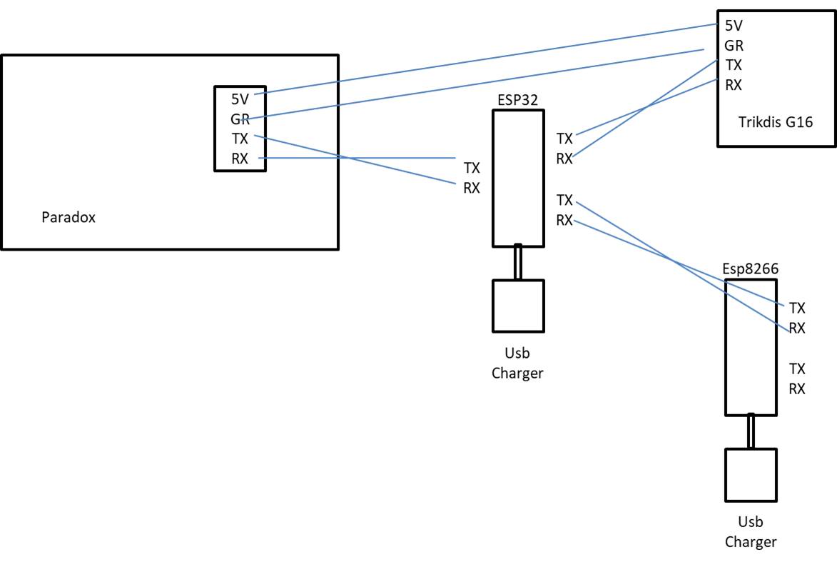
So, I need to connect my Paradox SP 6000 system to 2 different devices through the one and only serial port of the Paradox. I have been told that this can be done with a ESP32 device.
Background.
The paradox alarm system has 1 port with 5V-Ground-TX-RX
I have connected to this port a universal GPRS module in order to send reports to the security centre
I need to connect also a esp8266 wemos d1 mini pro in order to send the paradox status in my home automation system (Home Assistant) through mqtt.
In my esp8266 module I have installed this code
Right now if I connect each device separately are working fine but I can not connect both them simultaneously.
So here comes the help I need with the ESP32. I would like to work as a “splitter” (?) for the original signals. Please see the photo below.
A friend of mine told me that this is something relatively easy to achieve for someone knows about coding (he doesn’t)
Can someone help on this?
** I know that the eps8266 code could be implemented in ESP32 but I think it will be easier for me to debug if each device do only a part of the job
Since I am not good at all at programming and electronics, and as English is not my native language probably I didn’t explain well what I am looking for.
I need the TX of Paradox to be received in ESP8266 + in G16
Yes, and to control ESP8266 also (I am not sure what you mean with “control”
Yes it could, however if I was provided with the code I need and try to test it and didn’t work I am not sure how I could know where the problem is.That’s why I would prefer to have the esp8266 also.But I sure could give it a try with esp32 only.
It is at 5V (I am 99% certain). Since G16 is working ok when it is connected to Paradox UART right now I am trying to eliminate with usb connection for both ESP32+ESP8266
Both G16+ESP need to transmit data to paradox.
I think that it will be very rare to transmit both to the paradox at the same time. I don’t know if there is a way to avoid it. If for example I could set a priority I would give it to G16 I think.
What’s the baud rate? If it’s slow (like 9600) and there’s some processing time involved in commands, this could well happen and it can be quiet un-debuggable.
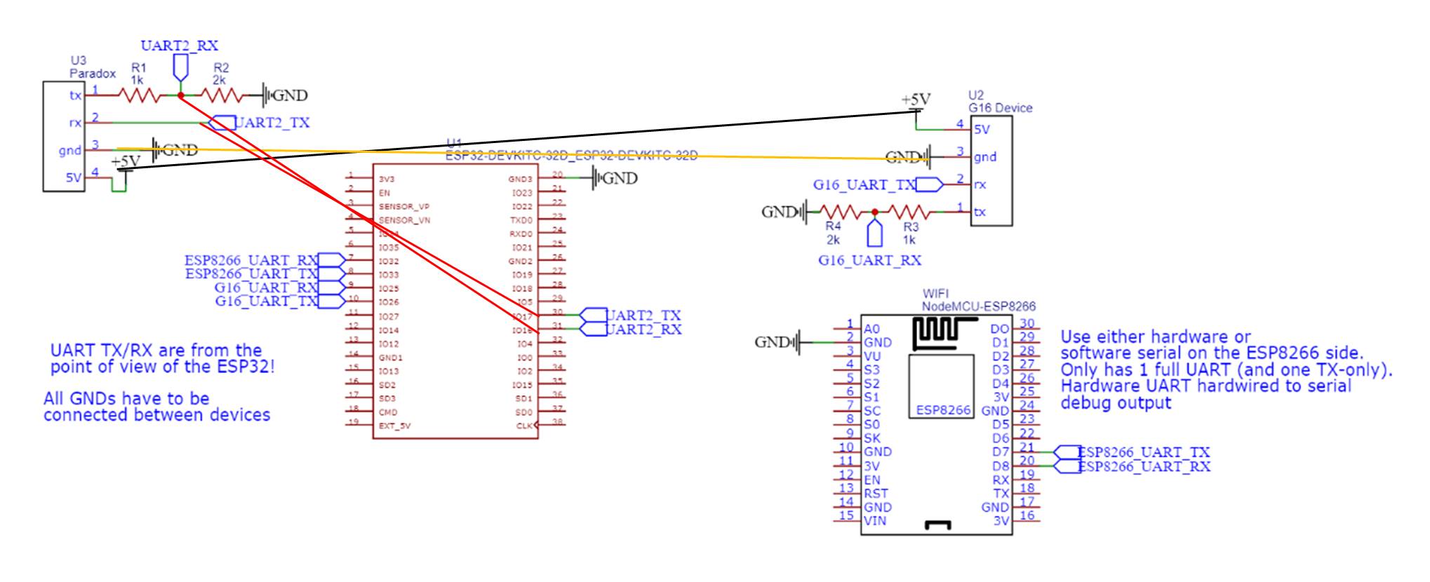
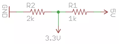
Also be aware that you do need a logic level conversion circuit if you’re working with different logic voltages. Connecting the 5V TX of the paradox to the ESP32 RX (which is a 3.3V device) will damage it. On the other hand, connecting a 3.3V TX to a 5V RX is still OK because 3.3V is high enough for a 5V logic device to be registered as a logical “high” / 1 – although, proper voltage conversion should be done here anyway. That can be done with digital logic level shifters or a simple voltage divider (only downwards conversion) .
So what you’re trying to build is a bus master / arbiter. The ESP32 is the arbiter which grants acecss to the UART port of the Paradox to the 2 participants G16 and ESP8266.
This problem might seem trivial at first, but depending on the device’s behavior can be very tricky.
Imagine: The ESP32 sends out all received characters from the Paradox to both the G16 and the ESP8266 at the same time. Every byte received at either the RX G16 or RX ESP8266 is immediately transferred to the Paradox.
What happens when the ESP8266 sends some status request command? The command is sent to the Paradox, and the received characters are transferred to the G16 and ESP8266. Can the firmware of the G16 cope with sudden unexpected data for which it hasn’t sent any previous command itself? Same when you switch the G16 and ESP8266 role. If the firmware can’t handle this, it might be necessary to redirect the UART data from the Paradox only to the device which has last sent a command to it.
But then if the Paradox periodically sends status messages itself, such a ‘redirect’ method won’t work either, and the previous broadcast / data duplicator approach should be used.
So is the Paradox operating in a command-answer manner and you need a “exclusive redirector” or just a very simple broadcaster (in Paradox TX → 2 RX direction) and forwarder (in 2 TX → RX direction)?
Although I can understand what you are saying (thanks for the lesson) unfortunately I don’t know the answers and also I don’t know how to check the above (baud rate,very simple broadcaster or exclusive redirector).
Is there a way to find that out?
For baud rate: You can hook up a USB-UART adapter to your PC and sniff the RX line (with also GND connected of course). Try different baud rates until something sensible is being sent. For that you might need some external interactor so that stuff is being sent. A deeper analysis can also be done by using a logic analyzer.
If this works out of the box you can probe the UART settings from the interaction with this thing or check the standard baud rates (9600, 115200,…)
For voltages: If you disconnect the devices from anything else but power, the device’s RX or TX line is usually pulled-up to the logic voltage. So just use a multimeter in volt mode for that.
The operation mode of the device can only be found out by looking at the data traffic sent between devices. You can also just assume one mode and program a firmware for that. As a prerequisite for that, you do have to know your device’s voltages for level conversion and the used baud rates though in any case.
Well, I don’t have the tools for that (at least right now) nor the knowledge to check them (ofcourse)
I thought it was much simpler than this.
That ESP32 could work as a simple repeater and that paradox could deal with the Rx messages.
I have to see what I can do in order to find out the above figures.
Thanks a lot for your time!
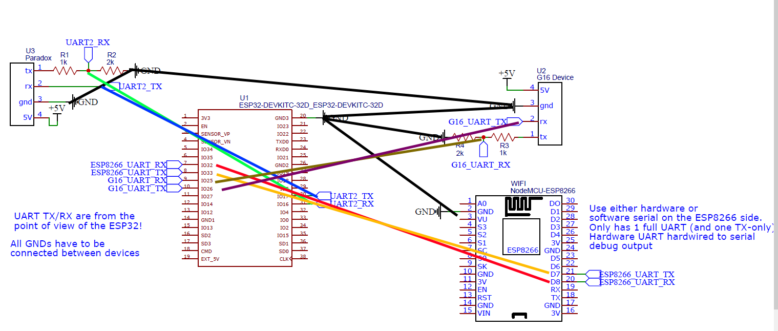
Schematics are included in the library. 5V → 3.3V via voltage dividers. No 3.3V → 5V conversion done (should still be ok as a hack). Since I don’t have these device here, I can’t really test it.
Thanks! I will try it tomorrow.
Since I haven’t code anything with platformio yet can you suggest me please a link to instructions to use it as a guide?
Oh. I think it’s best to download Visual Studio code, then the PlatformIO plugin. You can then clone the repository (download ZIP button in the upper right corner), extract it and open the project, and build and flash to the ESP32 from there. See download and documentation.
More importantly is the ability to debug it and understand the system if something fails . Logic analyzers, multimeter and a basic assortment of electronic components is really vital in embedded development.
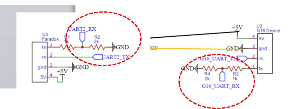
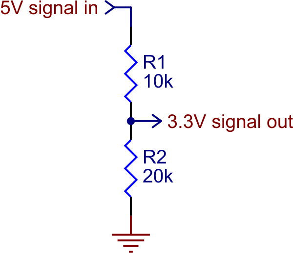
Again that at the end of that resistor, the GND has to be connected. The 2 resistors implement the voltage divdier to convert a 5V signal into a 3.3V one
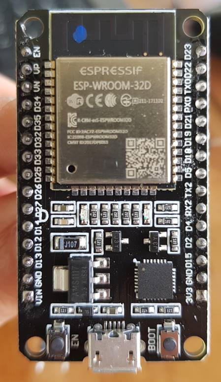
No you just have to attach the signals at the right I/O pins of the module. I justed an ESP32 DevkitC as the base, but every board with the exposed pins should work (and if not they can be changed in software…). The schematic e.g. says that the RX of the Paradox is to be hooked up to the IO17 (UART2 TX) of the ESP32. That’s called TX2 on your board. Also IO16 is RX2 on your board. The rest is the same, IO32 from the schematics is D32 on your board (left side), same for IO33, IO25 and IO26.
First of all, thank you very much for all these informations you are giving me.
I have to study a lot in order to understand and implement what you are suggesting, but I am happy with it because it is something I always admired and found difficult to understand by myself.
Please tell me if I understand right regarding the GNDs. At the end I have to connect the 3 GNDs from paradox,G16 & ESP8266 at GND3 (No 20) in yours schematic? and GND at my ESP32 in the bottom left according to my picture?
I also have to buy some resistors because I don’t have any. Is there a link that you could give me please just to be sure what I have to order?
So for the voltage dividers you need resistors (preferable axial / through-hole type) of resistnce value 1k Ohm (or “1000 Ohm / 1000Ω / 1000R / 1 kilo ohm”) and 2k. Resistors are extremely cheap and usually sold as bundles of many with many resistor values.
Also two resistors in series are logically one resistor with the combined value, so I connect 1k and 1k after another, that’s 2k (see Series and Parallel Circuits - SparkFun Learn) So you don’t even explicitly need the 2k one. (Also the next commercial value would be 2.2k). The wattage (power disippation the resistor can handle) doesn’t matter because it’s low in a voltage divider, so 1/4W or 1/8W or whatever works. The tolerance in % also doesn’t really matter but lower is better (+/- 1% tolerance on the resistence value is better than +/- 5%).
(Side note: For a voltage divider, only the ratio of the resistence values are important. A 5V → 3.3V conversion ratio can also be achieved by e.g. 10K and 20K)
For connecting the resistors and cables you might want to prototype things on a breadboard and using jumper wires, but of course also cable crimps and direct soldering can be used (though I would only do that after confirming it works in the configuration). So any set of breadboards like Amazon.com and a jumper / “dupont” cable assortment like Amazon.com (make sure there are “male-male, female-male, female-female” ones for different combinations of connector ends) will work.
