I’d like to re-purpose one of these boards for use on devices other than 3d printers.
Perhaps I’m biting off more than I can chew here, but I do have some limited experience in programming with an Arduino in the past, and appears on the surface that is all these boards really are…with some very useful added built in hardware of course that could be used for all sorts of stuff other than printers.
What I’m trying to do is control the onboard hardware, and access any available GPIOs through my own Arduino scripts. The marlin firmware seems pretty complex, but for the most part not needed, as I don’t intend to use it in a printer. So I’d like to strip as much of the ‘3d printer’ parts of it as I can to simplify things, or add in only what is needed for control over things.
Could someone point me in the right direction, or let me know what I may be up against in this en-devour?
If you want to treat the printer main board just like a microcontroller board, that’s totally fine. You just have to setup a basic project for the microcontroller target and define a way to flash the firmware on it.
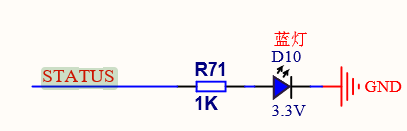
Together with code from like the blinky example but with the Blinky LED changed to PA15 (this is connected to the STATUS LED D10 on the board) that should be a good test firmware.
How to upload the firmware? The printer firmware includes a custom bootloader which can accept new firmwares via an SD Card. However it would be really tideous to keep using that because then you need extra code to relocate the compiled firmware a little further back into the flash as to not overwrite the bootloader. So I’d recommend to not use that preinstalled bootloader but go with a plain vanilla firmware.
Now by default it will try and use an STLink v2 for uploading the firmware. As you can see in PlatformIO’s board doc there are multiple ways to upload the firmware, which you have to define by the upload_protocol = ... directive in the platformio.ini.
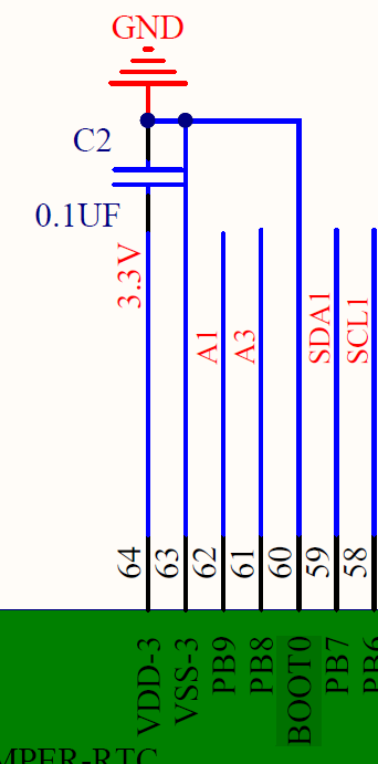
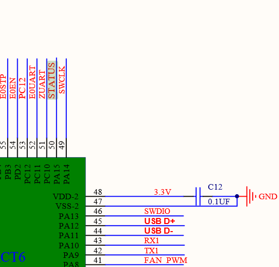
stlink: Expects a STLink plugged into the computer’s USB port and be connected to the SWD signals (SWDIO, SWCLK, GND, 3V3) on the powered board. As you can see in the linked schematics, these signals are available on the J10 Jumpercable connector (RESET, SWCLK, GND, SWDIO, 3.3V).
dfu USB-DFU Uploader. Normally you would need to put the STM32 controller into bootloader mode by powering it, then pulling the BOOT0 pins of the controller to 3.3V (refer here) and resetting the board via the RESET button. This makes the device appear as a USB-DFU device to your computer to be flashable. However, the schematics of boards make this impossible, since BOOT0 is hardwired to GND to always boot the flash firmware and never into the internal bootloader, so you can’t actually use this… (without cutting a trace).
serial: the UART version of the internal STM32 bootloader. Also impossible since you cannot put the controller into the internal bootloader mode.
Short summary: In VSCode (or pio commandline tool), generate a default Arduino project for the genericSTM32F103RC board, add a blinky code for an LED on the board, connect a cheap STLink programmer to the board, power it, and compile and upload the firmware, and you should have a working development environment (thanks to the STLinkv2 debugger probe, also step-by-step live debugging) with your 3D printer board.
@a67428 - did you ever get this working? I’m going down the same path at the moment myself
@maxgerhardt - I’ve created a simple arduino sketch and compiled for the board, but it doesn’t seem to work correctly. I’m not sure if the firmware is updating correctly - it seems to flash from the SD card and when I do it no longer connects to the computer. But it doesn’t work - a simple blink to external LED has no effect, and the skr is no longer connected to the computer. All I can do is flash the standard stock marlin back to the board and it starts working again (at least connects to my PC)
Do you have an STLink connected to the STM32 chip so that line-by-line debugging can be done on why the firmware doesn’t work (also uploads the firmware in a more direct way)
thanks for the reply - I don’t have an ST Link at the moment, I have ordered one
was tring to get this working just over SD card update
Things I’ve tried:
running code on Arduino board - works
changing pins - no work
trying to use internal pins/leds - no work
updating Marlin firmware to perform the blink - works
compiling in different environments (tried platformio and arduino) - no work
To complicate things this board does not have a built in debugger so I’m having trouble even just tring to get a serial connection. When Marlin is running on the board I can connect via pronterface over usb and send commands. When my firmware is running, I can’t get any connection to serial going, though I haven’t gone very far down that path.
That’s it. I compile to firmware.bin file, copy to SD card and connect to usb to power the board. The status light blinks a couple of times and firmware.cur is created but the board is non-responsive. The power light is on, but no-one is home.
I’ll go through the post linked you linked here and see if it helps
Are you probing the right pin there and have the LED in the right direction? Anyways, if you do PA15, this is the STATUS signal connected to an on-board LED and should work better
I’ve also double checked possible error causes regarding clock setup and found none. The schematics show that a 8MHz crystal is present, and this is also what the used Arduino board variants expects, do to a HSE+PLL setup to 72MHz. The prescalers and multipliers were checked with STM32CubeMX.
Can you also try in the code to do PA_15 instead of PA15, this will in turn call another function with a PinName argument instead of the usual int with pin mapping logic.
If still no LED lights up it can only be sensibally checked with a debugger.
(Also note the first post when doing this – uploading directly with this method will overwrite the bootloader of the device, so you should back that up first if you want to go back, e.g. with ST-Util)
I just tried PA_15 instead of PA9, with no change in function. No blink, no connection to my laptop
Tried the serial write and debug_flags from the other post as well, with no change
I’ve send a message to BigTreeTech but otherwise stumped. Obviously firmware can be compiled for this board per Marling and Klipper, it’s annoying that a simple sketch won’t work
With that code there also isn’t supposed to be a conncetion, it doesn’t initalize anything that something to do with the USB. For fun you can try this adapted platformio.ini
Yeah - nothing seems to get the board responsive - I’ve worn the damn thing out trying to get it working. Only thing that brings it back is flashing stock Marlin. Glad it’s not just me and I’m not doing something obviously stupid
I guess the problem is, that there is a bootloader on the SKR. This makes it necessary to rellocate the application code to another flash address. Otherwise it will not be able to run.
The application start address must be 0x08007000 instead of 0x08000000.
Hi @fattyboombatty, any lucky getting it to work eventually if you can remember from that long ago lol? I have been trying to do the exact same repurposing but on the SKRV1.4 Board which uses an NXP LPC1768 mcu. No luck getting the LED to actually blink despite the firmware.bin file changing to a firmware.CUR file after flashing firmware on SD Card and even tried using a USB to UART adapter to flash the firmware onto the board’s ISP bootloader via flashmagic and still nothing.
This thread is about the SKR mini e3 v1.2 which has a STM32F103C8 instead of your LPC1768. So I hope you didn’t use any of the platformio.ini files here to create your project.
There is also a similiar thread in How do I set my start offset(Bootloader) which matches your LPC1768, uses the official nxplpc platform and the mbed framework.
Thanks so much @maxgerhardt for providing me with some resources to check out! I hadn’t used any of the files here to create my project as I was aware of the differences between the microcontrollers. I will see how I go following your base project and checking out the similar thread as a first resort.