You need different debuggers for the STM32 and ESP32 unless you buy a generic (expensive) debugger such as Segger. They also use different signals, ARM SWD vs JTAG. Both though have relatively inexpensive debuggers from the vendor such that you don’t need to spend hundreds of dollars.
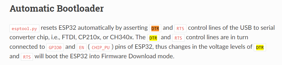
RTS/DTS are used for the reboot sequence such that when you flush through the USB, the ESP32 enters a bootloader mode to accept the new upload. They are standard on virtually all ESP32 boards thought some boards have a too small capacitor from EN to ground (I use 2.2 us) which make the mechanism not to work reliable.
If you want, you can also solder the jtag cable to the pins of the ESP32 dev kit, for debugging on the prototype. This is how I started.
And last thing, once you move to an RTOS, you will need of course to use synchronization when multiple tasks access the same resource, semaphores, mutexts, queues, and so on. Single threading Arduino style has it’s advantages.
The amount of different ESP32 mcu’s are overwhelming, too.
Which one would you recommend? I probably need a bunch of GPIOs.
The used dev board has actually too less pins and I workaround by combining LEDs of my buttons.
True, multithreading brings a whole new level of complexity.
The good news are, that with RTOS I can use threads, but I don’t have to
I am thinking about drawing the display or calculating a pitch angle in the background as separate threads …
I’ll have to figure it out. This probably will be a work in progress for a long time to bring the whole Arduino project to ESPIDF.
I went with the most basic one, ESP32-WROOM-32U-N4 (JLCPCB C328062). This is an external antenna version, I believe it’s ESP32-WROOM-32D. There is an identical one with an on board antenna. BTW, do you plan to run it on battery? The ESP32 in general is ‘power hungry’.
Thanks for all the detailed information.
I’ll have a closer look to the debugging problem. Including a custom ESP-Prog board would be an option. It’s still not completely clear to me how to use USB for UART and add debugger to the same port.
I am afraid, I do not have 4 signals left.
Need to figure it out, if and how I could use it. Anyhow, thanks for pointing this out
I probably will use an onboard antenna. Wifi/BT will only be necessary for configuration and not during operation. So it will be more convenient and at least not a hard requirement for now. But as I said, I want the hardware to be future proof and wireless connectivity is probably useful for new use cases
Thanks for pointing out the design guidelines. I noticed, that the antenna on all dev boards I’ve seen is on the edge, so I assumed there are some rules
Currently I have a few use cases when I connect the device to a smartphone via USB cable. This is only possible with Android for now, but I would love to make it iOS compatible via BT …
Yes, it’s a portable device and will be driven by a battery.
Currently I am using a 2400mAh LiPo. I was searching for a comparison of power consumption, and as far as I remember the ESP32 was at least not worse than the Arduino Due.
Unfortunately, I do no longer have the sources …
Now knowing it will be running on battery, would you recommend another MCU?
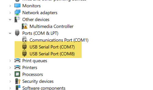
When I plug the debugger to the computer, I get two new devices in the device manager
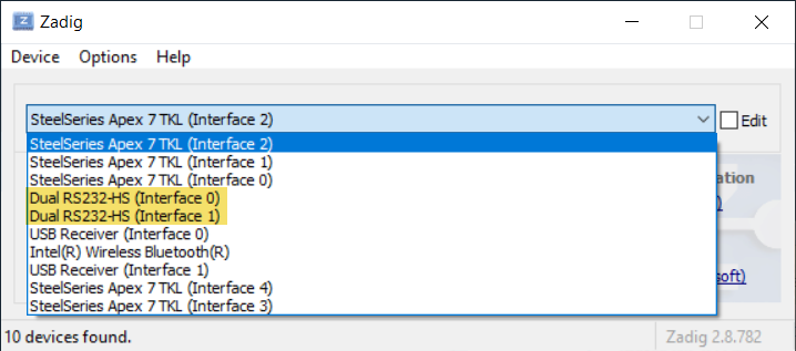
Then in the Zadig tool I see them as 0 and 1 and the debugger instructions tell you to configure interface 0 one as WinUsb and leave interface 1 as a COM device. I guess that interface 1 is the serial port you are looking for and that the FTDI ic has rx/tx pins for that interface. Never seen anybody doing it but I think it’s a great idea if it works, an ESP32 board with builtin hardware debugger,a single USB connector, and seamless integration with platformio.
Interesting.
I am working on macOS, but I do see a similar behavior for my AVR programmer.
I am using the AVR programmer for flashing the 16u2 IC of my current board, which acts as USB to UART bridge.
I’ve built a customer firmware to avoid resetting the main MCU, when connecting.
On Windows this can be prevented with the RTS signal, if I remember correctly. But on macOS it always resets…
I never used the other port. Was always wondering what it is for
If I got you right, then one port is the standard USB/UART interface and the other is the programming port/jtag port.
This is definitely something I would like to build
Hope I can make it work …
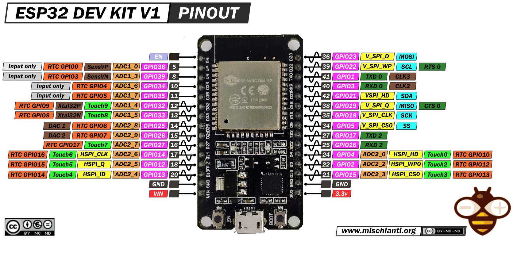
Still working on my schematics for the first prototype with the ESP32 DevKit.
On Mac I don’t need to manually reset the ESP32 when uploading. Platform IO uses esptool and it’s was designed to use the DTR/RTS trick. I think this is the same with the Arduino IDE which also uses the esptool. On my custom ESP32 board, I don’t even have a reset button or boot button. Never needed them.
Sorry, I was talking about Arduino Due.
As far as I know, the Due is kind of special as there is a magical baud rate of 1200 to bring the device in the programming mode. In that case, the Due will reset. One can prevent this behavior on Windows by suppressing the RTS signal, but on macOS (I even think on unix systems) it’s not possible due to the driver implementation.
That’s why I implemented a workaround. The controller does no longer reset when connecting with baud rate 1200. In addition I introduced another magical baud rate of 1800 to force a reset.
Typically on a Due it does not stand out, as the board is powered on as soon as the USB cable is plugged in. On my custom board, I do have a different schematic as I do not want to power the device on, while charging …
Anyhow, didn’t want to make it more complex
Just wanna say, that the AVR programmer also pops up as two usb devices