The problem
So, basically I bought a couple of D1 mini clones, I had no problem with the other two, but this one is giving me trouble.
When I try to flash it it just keeps blinking, and something that caught my attention was the output of pio device list:
/dev/ttyUSB0
------------
Hardware ID: USB VID:PID=0403:6001 SER=A50285BI LOCATION=1-1.2
Description: FT232R USB UART - FT232R USB UART
I’ve tried to find information about the topic but I’m quite lost. I’m open for help/guidance since I don’t want to just use another board and call it a day.
What I’ve tried
- A different cable, nothing changes.
- A different board, the other boards can be flashed.
- Using the FTDI wraper for
esptool, didn’t work
About my environment
- Arch linux with kernel 5.19.1
- Platofrmio (which I use from the terminal) 6.1.4
Thanks for the reply.
[env:d1_mini]
platform = espressif8266
board = d1_mini
framework = arduino
monitor_speed = 9600
lib_deps =
	crankyoldgit/IRremoteESP8266@^2.8.2
	bblanchon/ArduinoJson@^6.19.4
-
I’ts a small program I wrote and know it works, It was working for two months with another D1 (that I fried by accident a few days ago), also tried uploading the blink example from Arduino.
-
It fails, the error reads:
Verbose mode can be enabled via `-v, --verbose` option
CONFIGURATION: https://docs.platformio.org/page/boards/espressif8266/d1_mini.html
PLATFORM: Espressif 8266 (4.0.1) > WeMos D1 R2 and mini
HARDWARE: ESP8266 80MHz, 80KB RAM, 4MB Flash
PACKAGES:
 - framework-arduinoespressif8266 @ 3.30002.0 (3.0.2)
 - tool-esptool @ 1.413.0 (4.13)
 - tool-esptoolpy @ 1.30000.201119 (3.0.0)
 - tool-mklittlefs @ 1.203.210628 (2.3)
 - tool-mkspiffs @ 1.200.0 (2.0)
 - toolchain-xtensa @ 2.100300.210717 (10.3.0)
LDF: Library Dependency Finder -> https://bit.ly/configure-pio-ldf
LDF Modes: Finder ~ chain, Compatibility ~ soft
Found 37 compatible libraries
Scanning dependencies...
Dependency Graph
|-- IRremoteESP8266 @ 2.8.2
|-- ArduinoJson @ 6.19.4
|-- ESP8266WebServer @ 1.0
|   |-- ESP8266WiFi @ 1.0
|-- ESP8266WiFi @ 1.0
Building in release mode
Retrieving maximum program size .pio/build/d1_mini/firmware.elf
Checking size .pio/build/d1_mini/firmware.elf
Advanced Memory Usage is available via "PlatformIO Home > Project Inspect"
RAM:   [====      ]  35.7% (used 29232 bytes from 81920 bytes)
Flash: [===       ]  29.6% (used 308893 bytes from 1044464 bytes)
Configuring upload protocol...
AVAILABLE: espota, esptool
CURRENT: upload_protocol = esptool
Looking for upload port...
Auto-detected: /dev/ttyUSB0
Uploading .pio/build/d1_mini/firmware.bin
esptool.py v3.0
Serial port /dev/ttyUSB0
Connecting........_____....._____....._____....._____....._____....._____....._____

A fatal error occurred: Failed to connect to ESP8266: Timed out waiting for packet header
*** [upload] Error 2
========================= [FAILED] Took 26.87 seconds =========================
make: *** [makefile:9: upload] Error 1

(44 de 44): upload] Error 1
Can you connect the “0” pin on the D1 mini with GND and press the RST button on the side, then upload again?
1 Like
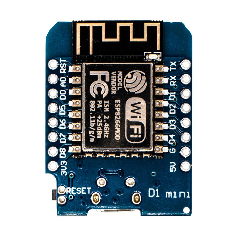
No luck. But just to be sure, my board is this one:
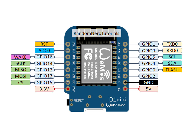
The “0” pin should be D3, right? I’ve tried with both D0 and D3 but no luck. I’m using this pinout as a reference:
Yes, GPIO0 is the one we want to ground so that the ESP8266 goes into bootloader mode.
If you did that and reset the board and it still wasn’t able to upload, then you might have dead hardware.
You can also just add monitor_speed = 74880 in the platformio.ini, then use the “Monitor” project task in PlatformIO to open the serial, then as GPIO0 is connected to GND, press the reset button. Does any text appear at all?
There’s no output, however, the esp light blinks.
Then some part of the hardware is defective. I wouldn’t bother further and get a new working board. If you want to investigate further, probe the TX pin of the board with a logic analyzer and see if there really is no output after all, or if it’s just the USB-UART converter on the board not showing you anything.
I was struggling too and thanks to your FT232 hint I found a FT232R driver called CDM_v2.12.36.2_WHQL_Certified
After installation it shows as “USB serial port COM6” in the device manager.