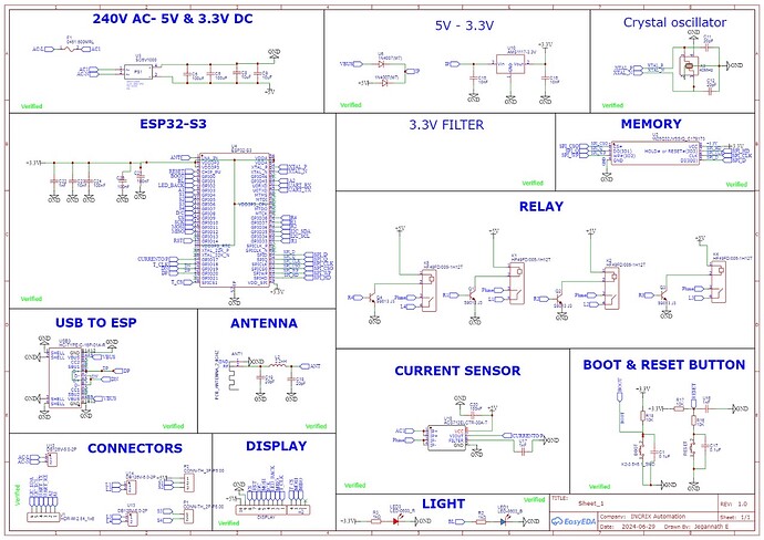
I’ve developed a custom ESP32-S3 development board designed with 4 relays for automation. when I connect the board via USB, it continuously disconnects and reconnects. This behavior prevents me from uploading any code.
I’ve checked the circuit design, including the boot button, which seems to be correct, but the problem persists. I suspect the issue might be with the memory chip or another component, but I’m not sure. I have attached the schematic of my pcb.
Does anyone have experience with this kind of issue or suggestions on how to troubleshoot it?
Some things I cross-referenced with https://docs.espressif.com/projects/esp-hardware-design-guidelines/en/latest/esp32s3/esp-hardware-design-guidelines-en-master-esp32s3.pdf and reference board:
- "To ensure the correct power-up and reset timing, it is advised to add an RC delay circuit at the CHIP_PU pin. The recommended setting for the RC delay circuit is usually R = 10 kΩ and C = 1 μF. " But you have R17 = 10K, U16 = 1nF
- The USB-C connector is missing the 5.1K resistors for the CC1, CC2 pins to GND, thus it might not correctly draw curent from it: https://hackaday.com/2023/08/07/all-about-usb-c-example-circuits/
- "The power trace should have a 10 μF capacitor on its way before entering into the
chip, and a 0.1 or 1 μF capacitor could also be used in conjunction. " → you only used 100nF, 10nF and 1nF, but no 10µF for 3.3V
- ESD diodes on the USB port neglected
- I’m not sure where there is no GND connection on any of the “Connectors”?
My recommendation would be:
- measure to check that +3.3V is stable.
- measure to check that RESET (CHIP_PDU) is stable
- Connect a separte UART-to-USB adapter to the U0TXD/U0RXD pins, broken out as “UART_RX/UART_TX” on J1 and observe the output at 115200 baud. The bootloader maybe prints helpful messages on there.
- Disconnect external devices from the borad such as the display
- Check that you have a 40MHz waveform on XTAL_P/N; with no clock, no startup.
