Basically, nothing is found. The truly interesting line here is
[W][esp32-hal-i2c.c:1413] i2cCheckLineState(): invalid state sda(21)=1, scl(22)=
If I change resistors to 3.3K or 2.2K, nothing changes. When I get rid of pull-up resistors, it changes to sda(21)=0, scl(22)=0. At this point I tried:
Changing CCS811 sensor, to no benefit
Changing resistors
Using esp-idf rather than Arduino bootloader
Changing ESP32 to a different one: JZK ESP-32S ESP32 Development Board
I must note that when I connect circuit to my Arduino Uno / Pro Mini everything works pretty much as expected, device can be found and I can communicate with it. I’m at my wit end. Any ideas what could be wrong?
Can you show what exact board you have there? Because there are RESET and ADDR pins on that chip that might be important.
Also have you tried another, preferrably 3.3V Arduino device like an ESP8266, with the standard I2C scanner sketch (yours has some stuff regarding EEPROMs inside), in case it’s something related to the I2C implementation in the Arduino core?
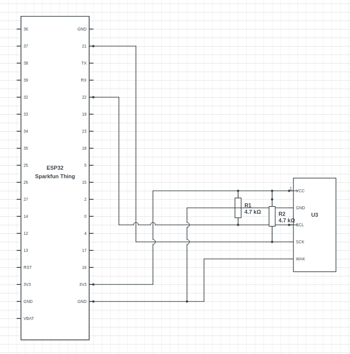
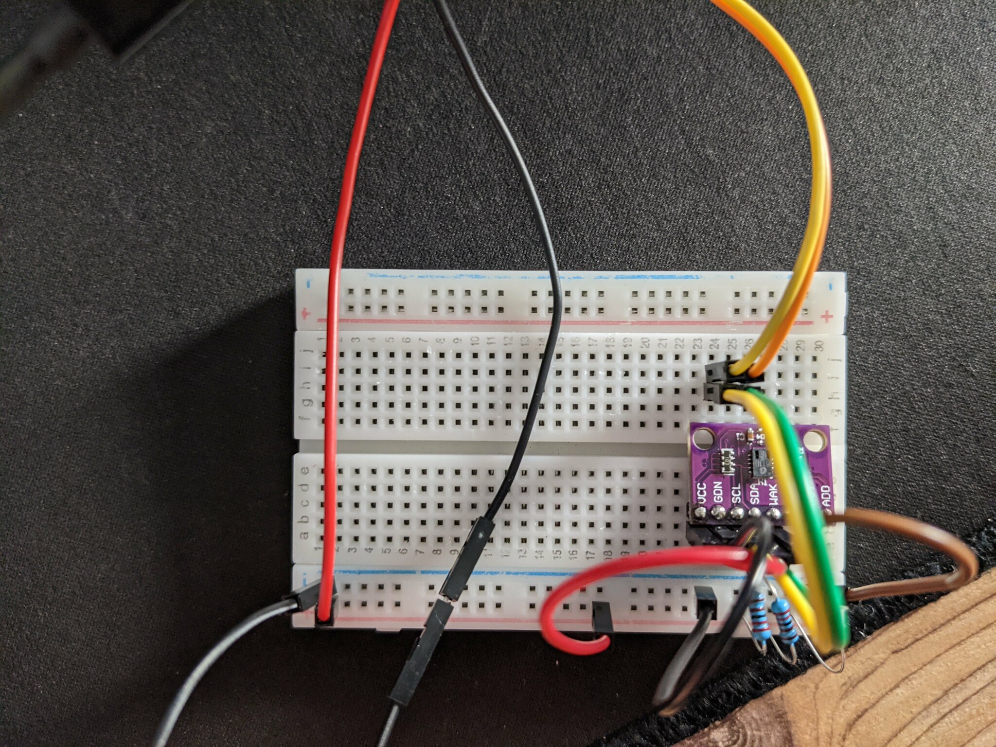
I don’t see a problem with the circuit per-sé. Doing WAK → GND should also be okay, although the datasheet at page 17 recommends connecting it to a GPIO pin while pulling it up with 4.7kOhms to do a software reset of the chip by pulsing LOW->HIGH->LOW and waiting a bit. I2C pullups also look sensible.
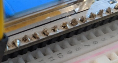
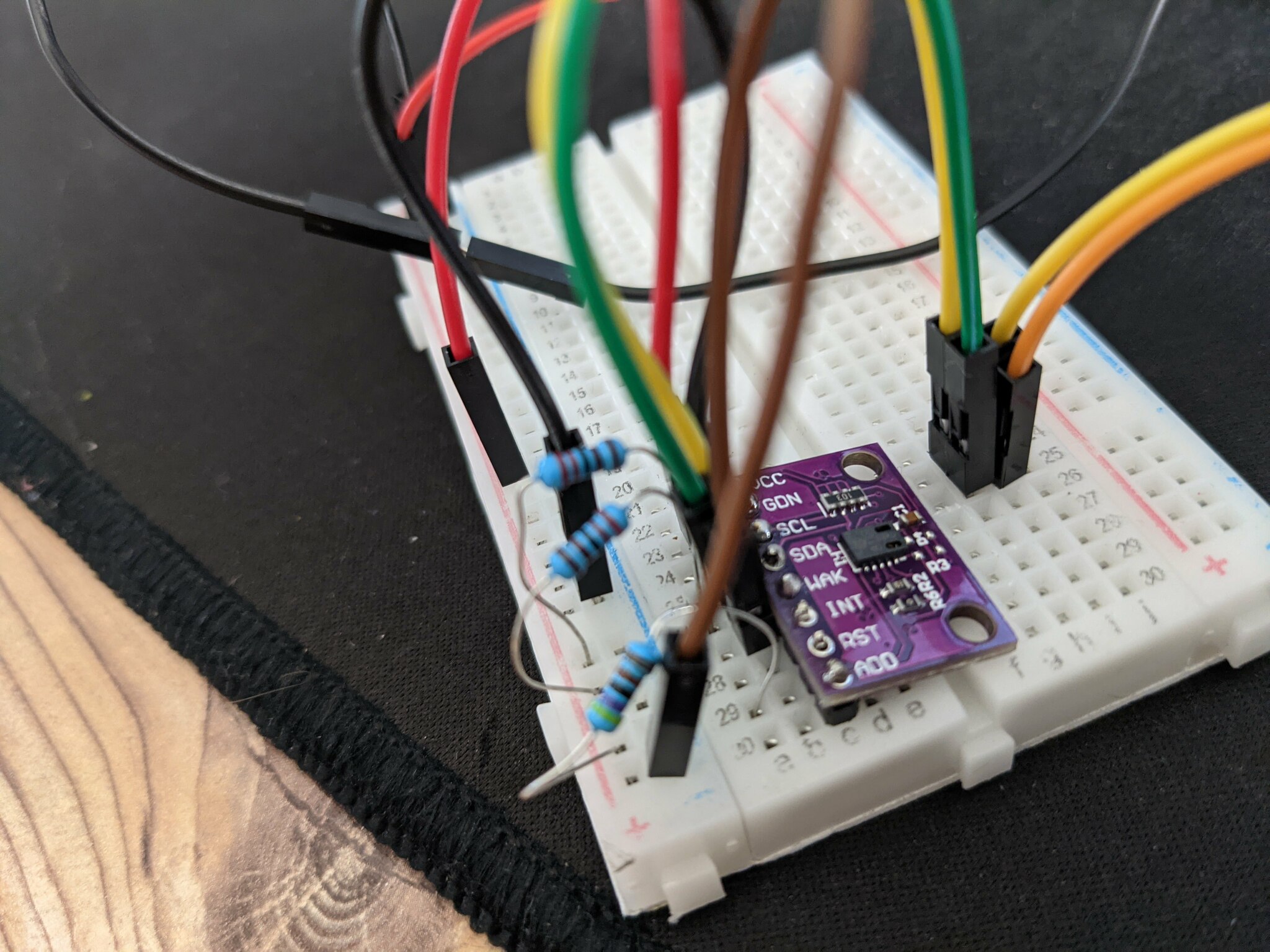
o_O every solder joint looks cold / incomplete. As in, just a little solder on top but not actually connected to the through-hole. Can you please take it out again and resolder all the pin hedears on the CO2 module? Just header the joint up and add more solder. I fear that none of them are making a connection.
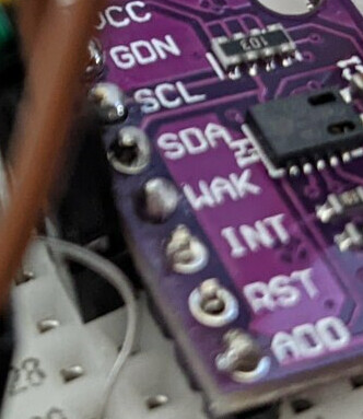
We can also then have a look at the RST and ADD pins which should probably be tied to some values… (if the resistor pack to the right of the chip doens’t do that already, but it doesn’t hurt).
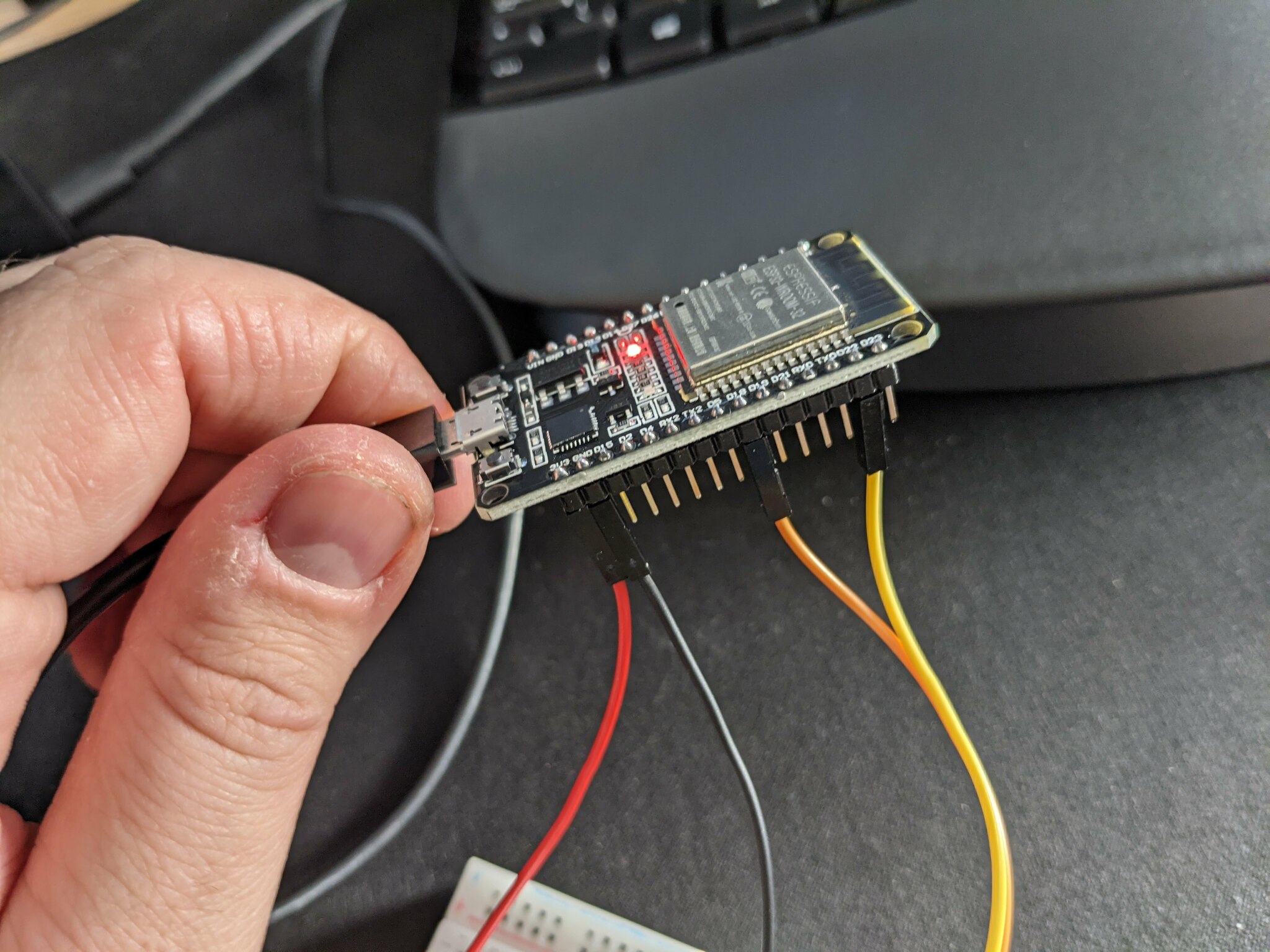
Actually when I’m looking closer at your ESP32 board I see the same type of problems.
Those might make connection, or might not make connection. You should reflow and resolder them again to be sure. The hole should be completelly filled with solder in this nice cone shape as seen in the video. Looks like your iron was not hot enough or you didn’t put it on long enough.
Actually that reminds me - when I was reading voltage off the SDA and SLC contacts it appeared to be nominal, but I’ll try with resoldering anyway. Thanks for your help!
Many thanks for your help so far. So I’ve resoldered the CCS811 and manually checked with multimeter connections between SDA/SCL and the corresponding components on the PCB - all looks sound. I also switched to another ESP32 (DoIT devkit) with pre-soldered header. None of this yield any results. I’ve also played with ADR, trying to set it to HIGH and LOW, again, without any results. At this point I’m starting to think that the problem is somewhere with I2C on ESP32 - because SPI sensors work great, and I can use I2C with this very sensor when connected to Arduino. Any other thoughts?
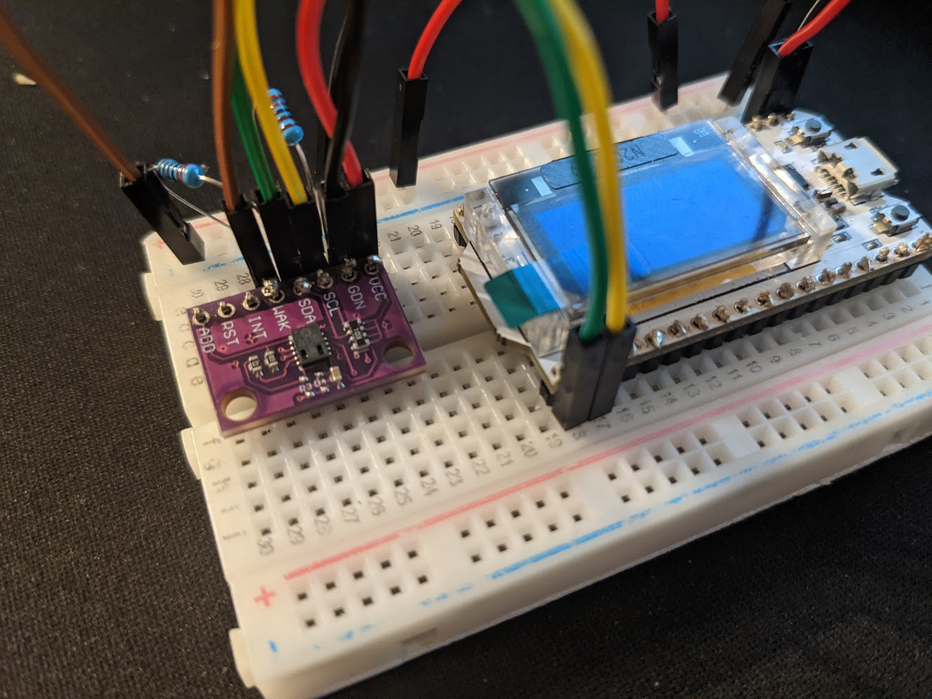
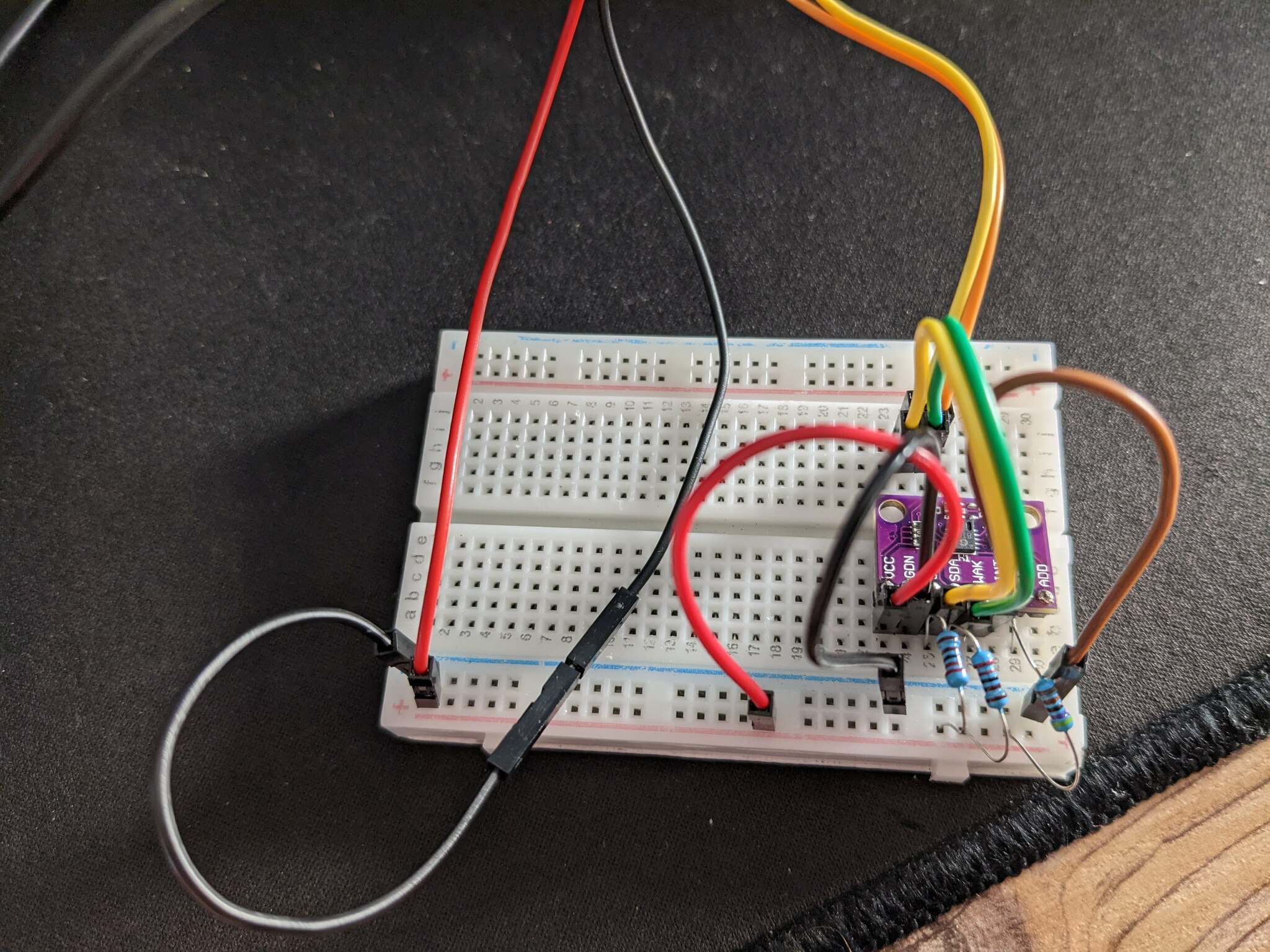
Yes, I’ve tried adding 4.7K pull-up to RST line (no obvious effect tbh). Here’re the photos of the new setup (my other ESP32 is less breadboard friendly so I’m using jumper wires to connect to it).
Tbh I am starting to think that this particular sensor (CCS811) has individual intolerance of ESP32. I’ve ordered an ESP8266 and will compare it to ESP32 as soon as I get it.
In your picture you’ve now connected SDL to pin 18 instead of 21. Does that make a difference when you run the I2C scanner sketch? Does removing the I2C pullup resistors make a difference? Can you measure the voltage on the board, e.g. over the capacitor C1, using a multimeter, to ensure it really gets 3.3V?
Max - that was it. I was just checking the schematic of the ESP32 I was using now, and I should’ve used 21 instead of 18. Things are working now. I want to check if absense or presense of pull-ups actually makes any difference just to document it for the history.
So pull-ups make no difference for the whole scheme to work. Now I only need to understand what was wrong with that other ESP32 and off we go. Thanks a ton for your help and patience throughout the process, at the very least I started soldering way more competently!
This is hopefully the final update. Apparently, for Heltec WiFi Kit 32 (WiFi Kit 32 (Phaseout) – Heltec Automation) one does need to use pull-ups (4.7K work well) – but for DOIT DevKit 32 (Zerynth | Documentation) things work out of the box. I think the recommendation here is to use pull-ups whether or not the board actually requires it, as this makes the schematic more portable.
Regarding the pullups: For I2C it’s just import that something, somewhere, pulls the otherwise floating SDA and SCL pins to VCC (here 3.3V) via some resistors (the resistor values depend on VCC and the I2C frequency and how fast the line should charge and discharge [parasitic capacitance]). The I2C lines SDA and SCL work on an open-collector/drain principle, meaning the microcontrollers can only force the line to GND by activating a transistor (BJT or MOSFET), but when the transitor is de-activated, the voltage on the line (with respect to GND) is pulled-up by the resistors.
In the previous picture I posted (an edit of yours), you see pretty nicely that the SCL and SDA pins go through the resistor pack marked “103” (SMD code for 10 kOhms) and to VCC. So the sensor board in this case has some weaker (=higher resistance value) resistors already on it. If those are not strong (low) enough, or if the ESP32 board does not have the pullups, then you can add a lower resistance value in parallel of that, so that the total resistance is lower. Also note that some chips can have internal weak pullup resistors on the GPIO pins which further affects the resistance.
So for that sensor board with builtin 10kOhm pullups, pretty much any board should work.