ESP32 sine wave with MCP4725 DAC, low frequency

Hi,

I am trying to generate a sine wave with my ESP32 DevKit C v4.
I’ve connected the Adafruit MCP4725 DAC via I2C and adapted the Adafruit examples.

I am creating a task for controlling the dac.

xTaskCreate(controlDac, "DAC", 25000, NULL, 2, NULL);

The task looks like this

#ifndef CONTROL_DAC_H
#define CONTROL_DAC_H

#include <Wire.h>
#include <Adafruit_MCP4725.h>
#include "sine.h"


Adafruit_MCP4725 dac;

void controlDac(void *param)
{
    dac.begin(0x62);

    while (1)
    {
        for (uint16_t i = 0; i < SINE_7BIT; i++)
        {
            uint16_t v = DACLookup_FullSine_7Bit[i];
            dac.setVoltage(v, false);
        }
    }
}

#endif

I used the 7bit look up table from Adafruit sine.h:

#ifndef SINE_H
#define SINE_H

#include "inttypes.h"

#define SINE_7BIT 128
const uint16_t DACLookup_FullSine_7Bit[SINE_7BIT] =
    {
        2048, 2148, 2248, 2348, 2447, 2545, 2642, 2737,
        2831, 2923, 3013, 3100, 3185, 3267, 3346, 3423,
        3495, 3565, 3630, 3692, 3750, 3804, 3853, 3898,
        3939, 3975, 4007, 4034, 4056, 4073, 4085, 4093,
        4095, 4093, 4085, 4073, 4056, 4034, 4007, 3975,
        3939, 3898, 3853, 3804, 3750, 3692, 3630, 3565,
        3495, 3423, 3346, 3267, 3185, 3100, 3013, 2923,
        2831, 2737, 2642, 2545, 2447, 2348, 2248, 2148,
        2048, 1947, 1847, 1747, 1648, 1550, 1453, 1358,
        1264, 1172, 1082, 995, 910, 828, 749, 672,
        600, 530, 465, 403, 345, 291, 242, 197,
        156, 120, 88, 61, 39, 22, 10, 2,
        0, 2, 10, 22, 39, 61, 88, 120,
        156, 197, 242, 291, 345, 403, 465, 530,
        600, 672, 749, 828, 910, 995, 1082, 1172,
        1264, 1358, 1453, 1550, 1648, 1747, 1847, 1947};

#endif

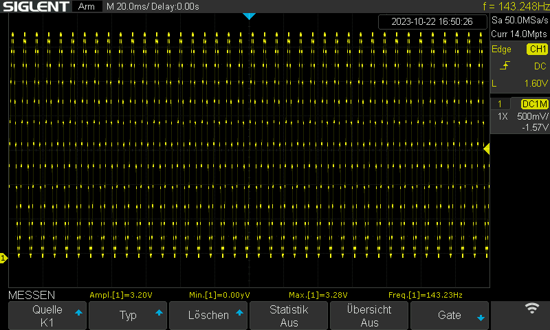
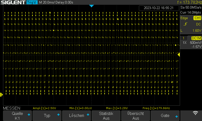
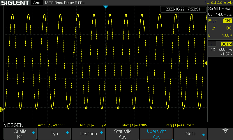
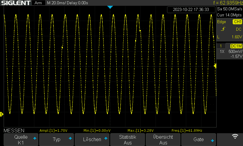
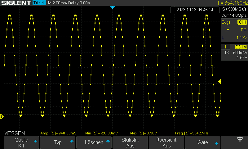
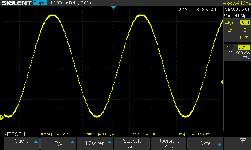
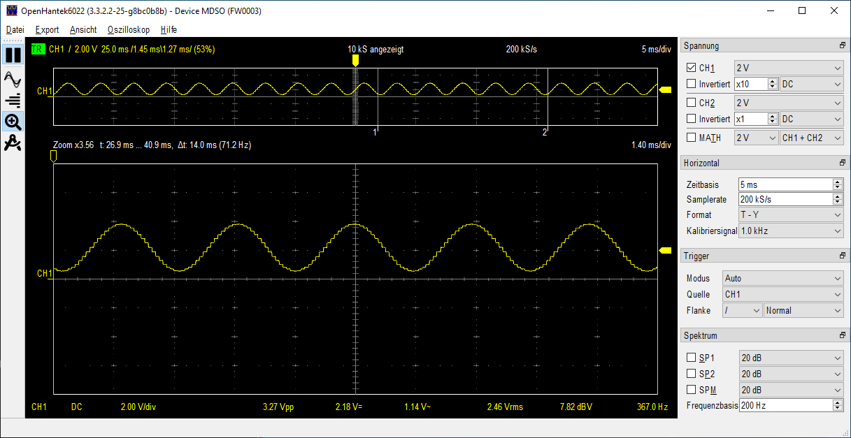
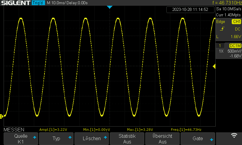
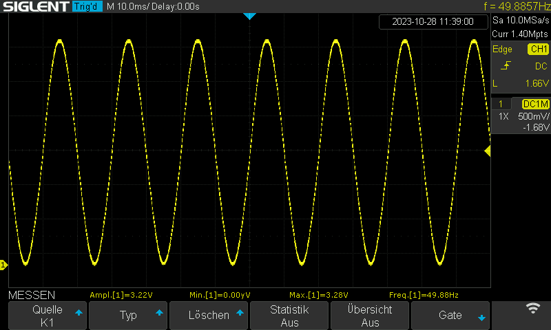
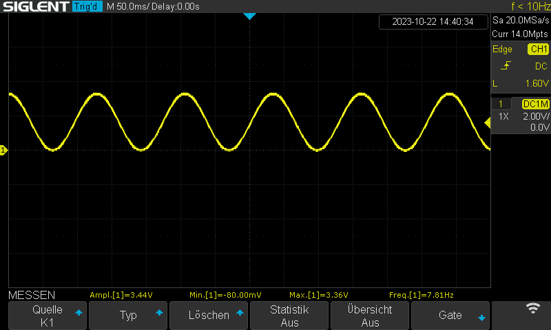
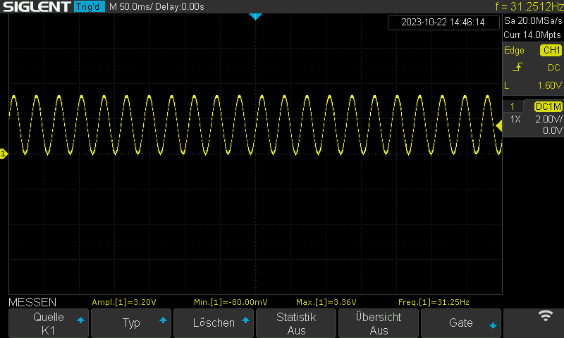
And indeed, I am getting a nice sine wave.
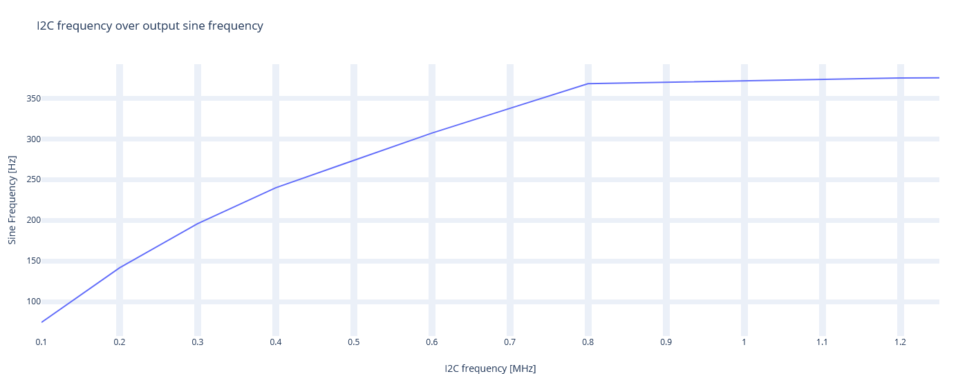
BUT the frequency is only ~7hz and I do not understand that.

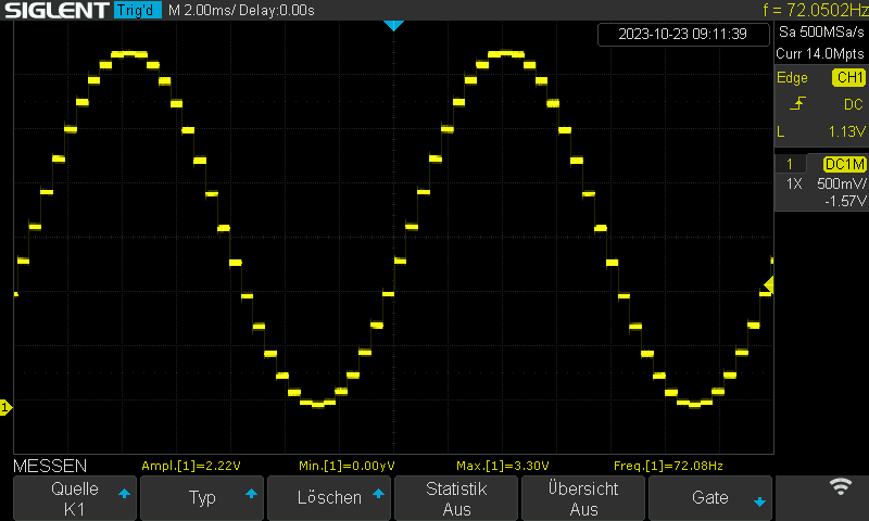
I can of course increase frequency by reducing the precision by using 5bit. But still then I cannot surpass ~31Hz.

The CPU is running at 240Mhz and I was expecting, that much higher frequency should be possible.
I’ve seen many Arduino tutorials with this DAC and they achieve higher frequencies with slower hardware.

In menuconfig I’ve set the cpu frequency to 240Mhz (originally 160mhz was set), but that didn’t change anything.
It seems not related to the cpu clock. Is it really that slow? I have a few other tasks, e.g. for OTA.

Any guidance is welcome …
Thanks :slight_smile:

1 Like

Have you tried this in the most minimal example with no other code? Just run it in loop() instead of a separate task.

This way, side effects of other tasks in the firmware that could e.g. possible block I2C access via mutex can be excluded.

Good point, thanks!
I’ve removed all code and just run the following

extern "C" void app_main()
{
  Adafruit_MCP4725 dac;
  dac.begin(0x62);

  while (1)
  {
    for (uint16_t i = 0; i < SINE_5BIT; i++)
    {
      uint16_t v = DACLookup_FullSine_5Bit[i];
      dac.setVoltage(v, false);
    }
  }
}

and indeed, I get much higher frequencies.
I tried it with 5 and 7 bit.
What I do not understand is, that 5bit has lower frequency than 7bit.
But now, we’re in the same range as the tutorials.
5Bit:


7Bit:

Sorry, I’ve changed the scaling compared to the pics from my first post.

Then, I created only 1 task and run that code inside of it and the frequency is back to ~31 Hz.
How is that possible? Is there no way running that code in a separate task? Do I have to run in in the “main thread”?!

I do not have much experience with FreeRTOS/eps-idf …
I was hoping to overcome the limitation of single thread with esp32.

EDIT:
Even running the DAC task with highes priority, the frequency is ~31hz. Has a task such an overhead?

Multiple things:

  • only ~150Hz still seems to be too slow by factor 10. The only thing that should be limitting the frequency is the maximum I2C frequency of maybe 400kHz (that is to write one sample, not one full wave consisting of e.g. 256 8-bit samples), because the CPU frequency is so high compared to that
  • Adafruit’s library has a lot of overhead since the actual sending of the I2C packet is nested in their abstraction layer, which is nested in the Arduino Wire abstraction layer, which is nested in the esp32-i2c-hal abstraction layer, which is nested in the ESP-IDF HAL abstraction layer, which is accessing the actual hardware registers…
  • Sending the to-be-output DAC value is extremely simple with this chip, only a 3-byte I2C packet is needed per this and this with no I2C setup packets needed. I’m not exactly sure why you’re having an ESP-IDF project and then still use Arduino-ESP32 (which is essentially an abstraction layer above ESP-IDF). Try keeping the project ESP-IDF only and use the ESP-IDF I2C master APIs directly to write those 3 bytes to the specified address. See example code.
  • Creating a task with a while(1) loop without any delays or mutex acquisitions might cause thread starvation on that CPU if that tasks wants all the CPU time.
  • Maybe assinging the task to core 1 instead of 0 makes a difference.
  • try using a pure Arduino project (framework = arduino) with their verbatim test sketch. Does it behave differently?

Oh actually I’m wrong here.

If the SCLK frequency is 400kHz, which is a bit frequency, and every sample (no matter 9, 8, 7, 6, 5 bit…) is sent as a 3-byte I2C packet (=24 bit), and for one 7-bit sinewave there’s 128 samples, then the output frequency would theoretically be…

400 kHz / 24 / 128 = 0.1302 kHz = 130.2 Hz

So for the 400kHz frequency that library is using, that is correct (default third parameter, you could also try saying 3400000 in your sketch there).

However, that’s still not the limit according to the datasheet, which boasts a “high speed 3.4 MHz” mode and not only 100 / 400kHz I2C. With that, the calculation for the 7-bit wave wave would be a max output frequency of about 1kHz.

Thanks for your thoughts.

I’ve no experience with esp-idf, so maybe I am completely wrong.
I was hoping to get the best of both worlds, that why I am using esp-idf in combination with Arduino framework. I will have a lot of additional hardware and I would like to avoid to write a driver for each of them, as they already exist for Arduino framework.
That said, I would like to have threads and other stuff from the esp-idf and I thought it would not be possible with Arduino framework only?
For production, it would be probably the best to get rid of the Arduino framework, but I am afraid I have not the skills and time to re-write all existing libraries. Maybe I am wrong, and they can be easily ported to esp-idf?

hmm this is weird.
I do not get over ~43 Hz with 7bit resolution in the most basic example. Maybe the first measurement was wrong? With 5bit I get ~170Hz but I cannot reproduce the first measurement with 7bit.

7bit 400khz i2c:

7bit and 3,4Mhz increase frequency about 20hz:

Arduino-ESP32 is a precompiled version of ESP-IDF with added abstraction layers. You can equally use the (same) FreeRTOS APIs to start a new FreeRTOS task on the second core, et cetera. See xTaskCreatePinnedToCore and tutorial.

The only use case of ESP-IDF plus Arduino-ESP32 as an ESP-IDF component is when the settings of the precompiled ESP-IDF version are not suitable for your project. Which I don’t think is the case there.

Thanks for your explanations.
Currently, I have the following framework configuration in platformio.ini

platform = espressif32
board = az-delivery-devkit-v4
framework = arduino, espidf

If I got you right, I can change it to

platform = espressif32
board = az-delivery-devkit-v4
framework = arduino

and still use the underlying FreeRTOS task apis.

I did some further tests.
I followed your suggestion and replaced the Adafruit library with a few lines of code utilising the Arduino Wire api.

Its again the simples possible example:

extern "C" void app_main()
{
  Wire.begin();
  Wire.setClock(34000000);

  while (1)
  {
    uint8_t packet[3];
    packet[0] = 0x40;

    for (uint16_t i = 0; i < SINE_7BIT; i++)
    {
      uint16_t v = DACLookup_FullSine_7Bit[i];

      packet[1] = v / 16;        // Upper data bits (D11.D10.D9.D8.D7.D6.D5.D4)
      packet[2] = (v % 16) << 4; // Lower data bits (D3.D2.D1.D0.x.x.x.x)
      Wire.beginTransmission(0x62);
      Wire.write(packet, 3);
      Wire.endTransmission();
    }
  }
}

The CPU is running at 240Mhz, and the I2C bus at 3.4Mhz.
I think the default CPU speed is 160Mhz, that’s why I am mentioning this explicitly.
This could be my mistake yesterday, as I’ve several pio profiles and for each a sdconfig has been created. Maybe I was mixing up the profiles yesterday resulting in different CPU speeds …

With 5bit, I achieve ~350Hz

With 7bit, I achieve ~88Hz.

Based on your calculation, I would have expected other frequencies. Especially, as I am running the I2C with 3.4Mhz.

5bit: 3400 kHz / 24 / 32 = 4.4270833333 kHz = 4427 Hz
7bit: 3400 kHz / 24 / 128 = 1.1067708333 kHz = 1106 Hz

Now, when I let it run in a task the code looks like this

extern "C" void app_main()
{
  xTaskCreate(controlDac, "DAC", 25000, NULL, configMAX_PRIORITIES - 1, NULL);

  Wire.begin();
  Wire.setClock(34000000);
}

void controlDac(void *params)
{
    uint8_t packet[3];
    packet[0] = 0x40;

    while (1)
    {
        for (uint16_t i = 0; i < SINE_5BIT; i++)
        {
            uint16_t v = DACLookup_FullSine_5Bit[i];

            packet[1] = v / 16;        // Upper data bits (D11.D10.D9.D8.D7.D6.D5.D4)
            packet[2] = (v % 16) << 4; // Lower data bits (D3.D2.D1.D0.x.x.x.x)
            Wire.beginTransmission(0x62);
            Wire.write(packet, 3);
            Wire.endTransmission();
        }
    }
}

With 5bit running in task, I achieve ~72Hz

With 7bit running in task, I achieve ~18Hz

I cannot understand why this is happening.
I see, that a task brings some overhead, but the speed is decreased by factor 5.

Would you consider this as usual?
I thought it would enhance the speed, when running the function in a separate task (maybe even on a separate core) to ensure, that the timing is sufficient.

It feels like I am doing something wrong.

Technically that is risky because the controlDac function could be executed before Wire.begin() etc runs (FreeRTOS scheduler is already running when app_main() is entered). So the I2C init code should come before the task creation.

Also you could try and use xTaskCreatePinnedToCore to make sure the task launches on the less-busy Core 1 instead of 0.

Another point could be that the Wire library does not correctly setup the 3.4MHz speed to its fullest extent. The ESP32 is capable of 3.4MHz I2C per its datasheet, but as the datasheet of the sensor and the I2C specs say, it needs to have special settings like 1:2 on-off period for SCLK and a stronger driver to discharge the parasitic capacitance line on a down transition faster. A good, capable logic analyzer could be used to check what’s happening on the I2C bus and how much delay is between each I2C transaction.

I’ve ordered one of these MCP4725 breakout boards just to cross verify.

True, I noticed that myself and changed the order of the initialisation part. :slight_smile:

I actually tried running the code on core 1, but didn’t saw any noticeable changes.
Based on the documentation, I would say that 3,4Mhz bus speed should be possible: setClock() - Arduino Reference

I do have a Saleae logic analyser. Would it be sufficient for this purpose?

Thanks for your effort :slight_smile:

Yeah that’s actually wrong because the I2C HAL that the Wire.cpp code silentely limits it to 1MHz. I don’t know why yet, but ESP-IDF has the same comments on 1MHz max, when the ESP32 datasheet does say 3.4MHz is possible…

With both a Wire.h implementation and a direct ESP-IDF driver/i2c.h implementation at the 1MHz and for a 5-bit sine wave, I achieve a frequency of 367 Hz according to my cheap USB oscilliscope.

This should not be the limit yet, as 1. DMA is not yet used to more seamlessly output the I2C signal and 2. it’s still only 1MHz, leaving factor 3 on the table. I’m looking into that.

Output sine wave frequency also plateaus at about an I2C speed of 800kHz, signifying that the DAC just uses clock stretching to give itself more time to react to the I2C packet. Not unexpected, since the DAC datasheet does mention special I2C highspeed command byte and possible different address, which I have not yet looked into…

(disabling the I2C filters and pumping CPU freq to 240MHz allowed it to go up to 1.25MHz without hitting an assert).

In other news, the ESP32 cannot use DMA to accellerate I2C operations because… its DMA controller does not support the I2C peripehral.

Good Morning and thanks for your detailed investigation.
The hard coded limit of 1MHz is interesting and I would have expected something like that.

I just want to achieve a solid 50hz sine wave.
Would you mind sharing your code?
Did you use Arduino or esp-idf only for your tests?
Currently my biggest concern is, why the threads are that slow. If this is really not a problem of my setup/code, I asking myself why ever should anyone use these threads.

Is your test code running in the main loop?
Did you make a comparison between main loop and thread?

I’ve the feeling that my sine wave is suffering when another thread is currently selected to work. The weird thing is, even when running it on core 1 I see deformation of the sine wave.

My current code is pure Arduino (framework = arduino) with the code running in loop(). I have not tested this in an ESP-IDF or ESP-IDF with Arduino as a component project yet. 50Hz sine should be doable at 6, maybe even 7 bit resolution.

would you mind doing a small test when running this code in a own thread? :slight_smile:
It really bothers me, that the threads are that slow on a relatively strong hardware …

Well I’ve made a few observations:

  • using the ESP-IDF #include <driver/i2c.h> API is more stable for me than the Wire API
  • at 1MHz I2C and Wire API, the capacitance of the SCL line matters so much that if I touch it with my hand, the frequency goes up by ~20Hz. This does not happen when i2c_filter_disable(0); is done though.
  • running on core 0 or core 1 does not matter
  • since the loop() code is being run on core 0, when creating the wave send task to also run at core 0, they will fight for compute time in the scheduler. So loop() has to have a delay(1000); to put that task to sleep, or better, run the wave task on core 1
  • low priorities (0 to 3) decrease the output frequency significantly, probably as the tasks are starved for processing time by the scheduler

A 7-bit, 60Hz sine wave works fine and indepedent on core 1 with 800kHz I2C frequency. The maximum output since frequency there was 89.85Hz. With a 5-bit wave, it was 368Hz.

You can try this code that has a few changable settings with regards to where the code is running. It should procude a 60Hz sine no problem. Change the I2C address to 0x62 instead of my module’s 0x60 as needed.

#include <Arduino.h>
#include <driver/i2c.h>
#include <wave.h> // Where DACLookup_FullSine_7Bit etc is

#define I2C_MASTER_SCL_IO           22       /*!< GPIO number used for I2C master clock */
#define I2C_MASTER_SDA_IO           21       /*!< GPIO number used for I2C master data  */
#define I2C_MASTER_NUM              0        /*!< I2C master i2c port number, the number of i2c peripheral interfaces available will depend on the chip */
//#define I2C_MASTER_FREQ_HZ          1000000  /*!< I2C master clock frequency */
#define I2C_MASTER_FREQ_HZ          800000  /*!< I2C master clock frequency */
#define I2C_MASTER_TX_BUF_DISABLE   0        /*!< I2C master doesn't need buffer */
#define I2C_MASTER_RX_BUF_DISABLE   0        /*!< I2C master doesn't need buffer */
#define I2C_MASTER_TIMEOUT_MS       1000

#define RUN_IN_SEPARATE_TASK 1 // 0 or 1
#define CREATE_TASK_ON_CORE_x 1 // 0 or 1
// should be kept above 3
//#define TASK_PRIO (configMAX_PRIORITIES - 1)
#define TASK_PRIO (10)

#define CALL_OVERHEAD_US 1

int i2c_master_port = I2C_MASTER_NUM;
i2c_config_t conf = {
    .mode = I2C_MODE_MASTER,
    .sda_io_num = I2C_MASTER_SDA_IO,
    .scl_io_num = I2C_MASTER_SCL_IO,
    .sda_pullup_en = GPIO_PULLUP_ENABLE,
    .scl_pullup_en = GPIO_PULLUP_ENABLE,
    .master = {
        .clk_speed = I2C_MASTER_FREQ_HZ
    }
};

static void init_i2c() {
    esp_err_t err; 
    setCpuFrequencyMhz(240); // overclock CPU, needed to get minimum number of SCL clock cycles above 13
    // enables higher frequency and gets rid of weird capacitve influences
    err = i2c_filter_disable(i2c_master_port);
    if (err != ESP_OK) {
        Serial.println("i2c_filter_disable failed: " + String((int) err));
        return;
    }
    err = i2c_param_config(i2c_master_port, &conf);
    if (err != ESP_OK) {
        Serial.println("i2c_param_config failed: " + String((int) err));
        return;
    }

    err  = i2c_driver_install(i2c_master_port, conf.mode, I2C_MASTER_RX_BUF_DISABLE, I2C_MASTER_TX_BUF_DISABLE, 0);
    if (err != ESP_OK) {
        Serial.println("i2c_driver_install failed: " + String((int) err));
        return;
    }
}

static uint8_t i2c_buf[I2C_LINK_RECOMMENDED_SIZE(5)];

static void IRAM_ATTR send_one_wave() {
    // send one full wave
    uint8_t packet[3];
    packet[0] = 0x40;
    for (int_fast16_t i = 0; i < /*SINE_5BIT*/ SINE_7BIT; i++)
    {
        uint16_t v = /*DACLookup_FullSine_5Bit[i];*/ DACLookup_FullSine_7Bit[i];

        packet[1] = v / 16;        // Upper data bits (D11.D10.D9.D8.D7.D6.D5.D4)
        packet[2] = (v % 16) << 4; // Lower data bits (D3.D2.D1.D0.x.x.x.x)
        
        unsigned long t_start = micros();
        i2c_cmd_handle_t handle = i2c_cmd_link_create_static(i2c_buf, sizeof(i2c_buf));
        i2c_master_start(handle); // start
        i2c_master_write_byte(handle, (0x60 << 1) | I2C_MASTER_WRITE, true); // change address to 0x62 if needed
        i2c_master_write(handle, packet, sizeof(packet), false);
        i2c_master_stop(handle);
        i2c_master_cmd_begin(I2C_MASTER_NUM, handle, I2C_MASTER_TIMEOUT_MS / portTICK_PERIOD_MS);
        i2c_cmd_link_delete_static(handle);
        unsigned long t_end = micros();
        static constexpr unsigned long wave_60hz_us = 1000000 / 60 / SINE_7BIT;
        // to make the wave ~60Hz, compute how long one wave sample at 60Hz should be held,
        // then wait out the remaning time if we're faster, minus the overhead for doing that call.
        unsigned long sample_held_for_us = t_end - t_start;
        if (wave_60hz_us > sample_held_for_us + CALL_OVERHEAD_US) {
            delayMicroseconds(wave_60hz_us - sample_held_for_us - CALL_OVERHEAD_US); 
        } // else we're already behind schedule..
    }
}
#if RUN_IN_SEPARATE_TASK == 1
void waveTask(void* arg) {
    while(1) {
        send_one_wave();
    }
}
#endif

void setup()
{
    Serial.begin(115200);
    init_i2c();
    #if RUN_IN_SEPARATE_TASK == 1
    xTaskCreatePinnedToCore(waveTask, "wave", 8096, NULL, TASK_PRIO, NULL, CREATE_TASK_ON_CORE_x);
    #endif
}

// This runs on core 0
void loop () {
    #if RUN_IN_SEPARATE_TASK == 0
    send_one_wave();
    #elif CREATE_TASK_ON_CORE_x == 0
    delay(1000); // make sure this task doesn't steal compute time for Core 0 that's needed in the wave task
    #else 
    // if task was create on core 1, it does not affect core 0, and we don't need to need
    // to give up compute time
    #endif
}

This is with a standard platformio.ini of

[env:esp32dev
platform = espressif32@6.4.0
board = esp32dev
framework = arduino
monitor_speed = 115200

Hallo Max,

thanks for your continuing support - I really appreciate that.
I made some tests with your code and it seems much more stable than my stuff.
Not sure why, but it runs better :slight_smile:

My first try was to simply bring your code to my hardware. That worked pretty well.

Then, I tried to output 50hz and calculate the sine wave (and not use the LUT), as this is what I eventually want to achieve.


The offset can be reduced by fine tuning the CALL_OVERHEAD_US you’ve already introduced.

Then I brought back OTA in a separate task and also did the fine-tuning.
Voilà, I think that looks pretty good.