Esp32-s3: Serial<n> objects are silent

Hi

Disclaimer: yes, I’ve been through a lot of posts, but that did not help me (there must be something I dont get, therefore I hope for your help).

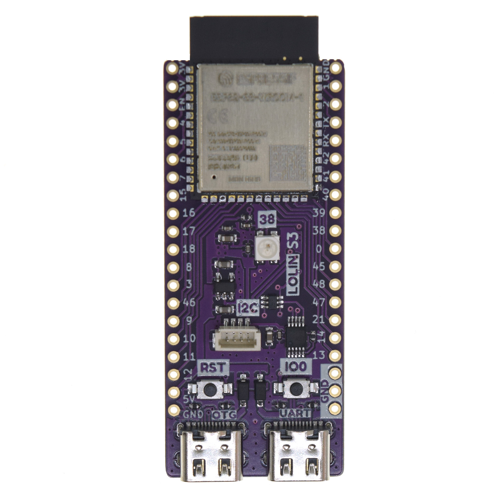
I am trying to understand how to see the text my program show through Serial, Serial0, Seria1 and Serial2 objects on the wemos LOLIN esp32-s3 board.

Using platformio on linux, minicom and my own USB-serial port bought at adafruit to try to connect to the various serial ports, here what I see

  • I get nothing from the USB ports of the board
  • if I put my adafruit serial pins on the pins of UART0 of the boards, I get this, which tends to prove I can get something out of the printf function.

So what do I need to do to see these Serial object actually do output something?

Thanks.

ESP-ROM:esp32s3-20210327
Build:Mar 27 2021
rst:0x1 (POWERON),boot:0x8 (SPI_FAST_FLASH_BOOT)
SPIWP:0xee
mode:DIO, clock div:1
load:0x3fce3808,len:0x44c
load:0x403c9700,len:0xbd8
load:0x403cc700,len:0x2a80
entry 0x403c98d0
printf
msg:HIGH
msg:LOW
(etc)

but nothing is visible from what my code sends through Serial, Serial0, Serial1 even when putting my adaftuit serial pins on the right pins for uart1 (17,18)

My code

#include <Arduino.h>

#define MYLED 4

#ifndef MYLED
#define MYLED LED_BUILTIN
#endif

void println(const String &s)
{
  printf("msg:%s\n",s.c_str());

  Serial.println(s);
  Serial0.println(s);
  Serial1.println(s);
  Serial2.println(s);
}

// the setup function runs once when you press reset or power the board
void setup() {
  // initialize digital pin MYLED as an output.
  delay(2000);
//  while(! Serial);

  pinMode(MYLED, OUTPUT);
  Serial.begin(9600);
  Serial1.begin(9600);
  Serial2.begin(9600);

    Serial.println("HIGH");
  digitalWrite(MYLED, HIGH);  // turn the LED on (HIGH is the voltage level)
  delay(2000);

}
int freq=1024;
bool decrease=true;
int nbflash=0;


// the loop function runs over and over again forever
void loop() {
  Serial.println("Serial no #");
  Serial0.println("Serial 0");
  Serial1.println("Serial 1");
  Serial2.println("Serial 2");

  printf("printf\n");
  
  println("HIGH");
  digitalWrite(MYLED, HIGH);  // turn the LED on (HIGH is the voltage level)
  delay(freq);                      // wait for a second
  println("LOW");
  digitalWrite(MYLED, LOW);   // turn the LED off by making the voltage LOW
  delay(freq);                      // wait for a second

  nbflash = (nbflash+1)%4;
  if(nbflash ==0)
  {
    if(decrease)
    {
      if(freq<=64) decrease=false;
      else freq /=2;
    }
    else
    {
      if(freq>=2048) decrease=true;
      else freq *=2;
    }
  }
}

My platformio.ini

[env:lolin_s3]

platform = espressif32
board = lolin_s3
framework = arduino
; change microcontroller
board_build.mcu = esp32s3
; change MCU frequency
board_build.f_cpu = 240000000L

upload_protocol = esptool
upload_port = /dev/ttyACM0

debug_tool = esp-prog
debug_port = /dev/ttyUSB0

build_flags =
-DARDUINO_USB_MODE=1
-DARDUINO_USB_CDC_ON_BOOT=1

The lolin s3 has two USB ports: OTG on the left and UART on the right - where “UART” stands for the UART0 interface of the ESP .

Depending on the USB_CDC_ON_BOOT value, the serial objects behave differently:

USB_CDC_ON_BOOT UART0 native USB (OTG)
0 Serial USBSerial
1 Serial0 Serial

Per lolin_s3.json USB_CDC_ON_BOOT default value is 1.

In this case

  • Serial0 object is routed to the UART connector
  • Serial object is routed to the OTG connector

Note: printf() doesn’t use the serial object.

You missed to initialize Serial0.
Everything that is output to Serial0 in your code does not go anywhere.

The boot message is output at 115200 baud. However, you are using 9600 baud in your sketch. I suppose that your minicom is set to 115200 baud (otherwise you would not have been able to read the boot message and the output of printf). You should adapt your code to 115200 baud.

Thank you, this is definitively the advice I was looking for.

This is what I observe now, after having fixed Serial0.begin and all speed to 115200

things that work

  • I can see Serial 0 (and printf) if I put my adafruit USBSerial on pins 43/44 (ttyUSB0) This is a big relief, at least something happens

  • I can see Serial 1 if I use pins 16/15 (As found in the HardwareSerial class code). These are not the pins 17/18 I was using according to the chip pinout.

Things that still dont work

  • I still cannot see anything from the OTG port as in this case there is no serial port declared from the OTG port on my machine
    to have a a port (ttyACM0), I need to reboot with the pin 0 down, but then the board is in program upload mode, it is not executing my code (no LED blinking).

  • If I plug my USBc cable in the UART port instead of OTG, the program runs but I cannot see any port on my machine. The lsusb does show a CH340 driver (which is not there if I dont plug that cable). Strange enough, it also removes the ttyUSB0 port of my Adafruit USBSerial (while still listed in lsusb). Even if I unplug the board, I need to unplug and re-plug the Adafruit USBSerial to see ttyUSB0 back.

Any further help would be appreciated!

Thanks.

1 Like

GPIOs 15/16 are correct per arduino-esp32/cores/esp32/HardwareSerial.cpp at 18bcca256bbc06f9aeb15642be5cf0072b533232 · espressif/arduino-esp32 · GitHub.

Which pinout of the chip are you referring to? The only pinout I found from wemos for the S3 is a bit poor. S3 — WEMOS documentation

Sounds like you need to install the correct drivers.
Since you’re on Linux I’m afraid I can’t help you with this.

I got from this document on the chip itself that the uart1 should be on pins 17/18.

(search for U1TXD / U1RXD)

I will try on Windows to check if this is a driver issue.

It’s curious what espressif has come up with.
I can’t explain the discrepancy.