Hi,
I need to process a worst case 2MHz manchester signal (1 Mbit) and want to give it a try with plain ESP32-S3 using High Level Assembler interrupts. I found a post that implements this scheme (ESP-IDF) and I am strugling to port it to PIO.
There is a chance the posted code has a flaw but I am not discarding that despite of being able to compile and upload, the code is crashing one time after the other.
This is the URL
High Level Interrupt Handler
This is how my PIO files look (some modifications based on other URL’s)
platformio.ini
[env:esp32-s3-devkitc-1]
platform = espressif32
board = esp32-s3-devkitc-1
framework = espidf
monitor_speed = 115200
In folder src I have 3 files
-CMakeLists.txt
-highint5.S
-main.c
CMakeLists.txt
FILE(GLOB_RECURSE app_sources ${CMAKE_SOURCE_DIR}/src/*.*)
idf_component_register(SRCS ${app_sources})
target_link_libraries(${COMPONENT_TARGET} "-u ld_include_xt_highint5")
highint5.S
#include <xtensa/coreasm.h>
#include <xtensa/corebits.h>
#include <xtensa/config/system.h>

//#include "freertos/xtensa_context.h" // deprecated now <xtensa_context.h>
#include <xtensa_context.h>

#include "esp_private/panic_reason.h"
#include "sdkconfig.h"
#include "soc/soc.h"
#include "soc/gpio_reg.h"
#include "soc/dport_reg.h"

#define L5_INTR_STACK_SIZE  12
#define L5_INTR_A15_OFFSET   0
#define L5_INTR_A14_OFFSET   4
#define L5_INTR_A13_OFFSET   8

    .data
_l5_intr_stack:
    .space      L5_INTR_STACK_SIZE

    .section .iram1,"ax"
    .global     xt_highint5
    .type       xt_highint5,@function
    .align      4
xt_highint4:

    movi    a0, _l5_intr_stack // assuming a0 saved restored by EXCSAVE_5
    s32i    a15, a0, L5_INTR_A15_OFFSET
    s32i    a14, a0, L5_INTR_A14_OFFSET
    s32i    a13, a0, L5_INTR_A13_OFFSET

    // Clear interupt on GPIO17
    movi    a14, GPIO_STATUS_W1TC_REG
    movi    a15, (1 << 17)
    s32i    a15, a14, 0
    memw

    // Toggle output reg (GPIO18)
    movi    a13, GPIO_OUT_W1TS_REG
    movi    a14, GPIO_OUT_W1TC_REG
    movi    a15, (1 << 18)
    s32i	a15, a13, 0
    s32i	a15, a14, 0

    // Increment intCounter
    movi    a14, intCounter
    l32i    a15, a14, 0
    addi    a15, a15, 1
    s32i    a15, a14, 0
    memw

    l32i    a15, a0, L5_INTR_A15_OFFSET
    l32i    a14, a0, L5_INTR_A14_OFFSET
    l32i    a13, a0, L5_INTR_A13_OFFSET

    rsr     a0, EXCSAVE_5 // restore a0
    rfi     5

    .global ld_include_xt_highint5
ld_include_xt_highint5:
main.c (had to include more #include files to compile) (changed “intr_matrix_set” to function “esp_intr_alloc” as recommended in other posts)
#include <stdio.h>
#include "sdkconfig.h"
#include "freertos/FreeRTOS.h"
#include "freertos/task.h"
#include "esp_system.h"
#include "spi_flash_mmap.h"
#include "driver/gpio.h"
#include "esp_intr_alloc.h"
#include "freertos/queue.h"
#include "soc/soc.h"
#include "soc/dport_reg.h"

#include "xtensa/core-macros.h"
#include "soc/periph_defs.h"
#include "esp_log.h"
#include "esp_rom_gpio.h"
#include "rom/ets_sys.h"

#include "soc/gpio_struct.h"

#include "esp_err.h"
#include "esp_attr.h"
#include "hal/cpu_hal.h"

#include "soc/gpio_reg.h"

#define GPIO_OUTPUT_IO_0    18
#define GPIO_OUTPUT_PIN_SEL (1ULL<<GPIO_OUTPUT_IO_0)
#define GPIO_INPUT_IO_0     17
#define GPIO_INPUT_PIN_SEL  (1ULL<<GPIO_INPUT_IO_0)

#define INTR_NUM 31
#define CPU_CORE 0

volatile int intCounter = 0;
volatile int regVal = 0 ;

static void gpio_task_example(void* arg) {

    intr_handle_t handle;
    esp_err_t err;

    // setup
	gpio_config_t io_conf;

	//disable interrupt
	io_conf.intr_type = GPIO_INTR_DISABLE;
	//set as output mode
	io_conf.mode = GPIO_MODE_OUTPUT;
	//bit mask of the pins
	io_conf.pin_bit_mask = GPIO_OUTPUT_PIN_SEL;
	//disable pull-down mode
	io_conf.pull_down_en = GPIO_PULLDOWN_DISABLE;
	//disable pull-up mode
	io_conf.pull_up_en = GPIO_PULLUP_DISABLE;
	//configure GPIO with the given settings
	gpio_config(&io_conf);


	//interrupt of rising edge
	io_conf.intr_type = GPIO_INTR_POSEDGE;
	//set as input mode
	io_conf.mode = GPIO_MODE_INPUT;
	//bit mask of the pins
	io_conf.pin_bit_mask = GPIO_INPUT_PIN_SEL;
	gpio_config(&io_conf);

	gpio_set_level(GPIO_OUTPUT_IO_0, 0);

	ESP_INTR_DISABLE(INTR_NUM);

    err = esp_intr_alloc(INTR_NUM, ESP_INTR_FLAG_LEVEL5|
ESP_INTR_FLAG_IRAM, NULL, NULL, &handle); // Must be LEVEL5
    if (err != ESP_OK) {
        printf("Failure: could not install ISR, %d(0x%x)\n", err, err);
        while (true);
    }

	ESP_INTR_ENABLE(INTR_NUM);

	while(1){

		printf("Task waiting for interrupts, count is %i\n", intCounter);
		printf("GPIO Reg value = %X", regVal);
		vTaskDelay(20000);

	}
}

void app_main(void) {
    printf("This tests the interrupt latency, plug in a fungen to pin 17 and observe on pin 18!\n");

    xTaskCreatePinnedToCore(gpio_task_example, "gpio_task_example", 2048, NULL, 10, NULL, 1);
    while(true) {}

}
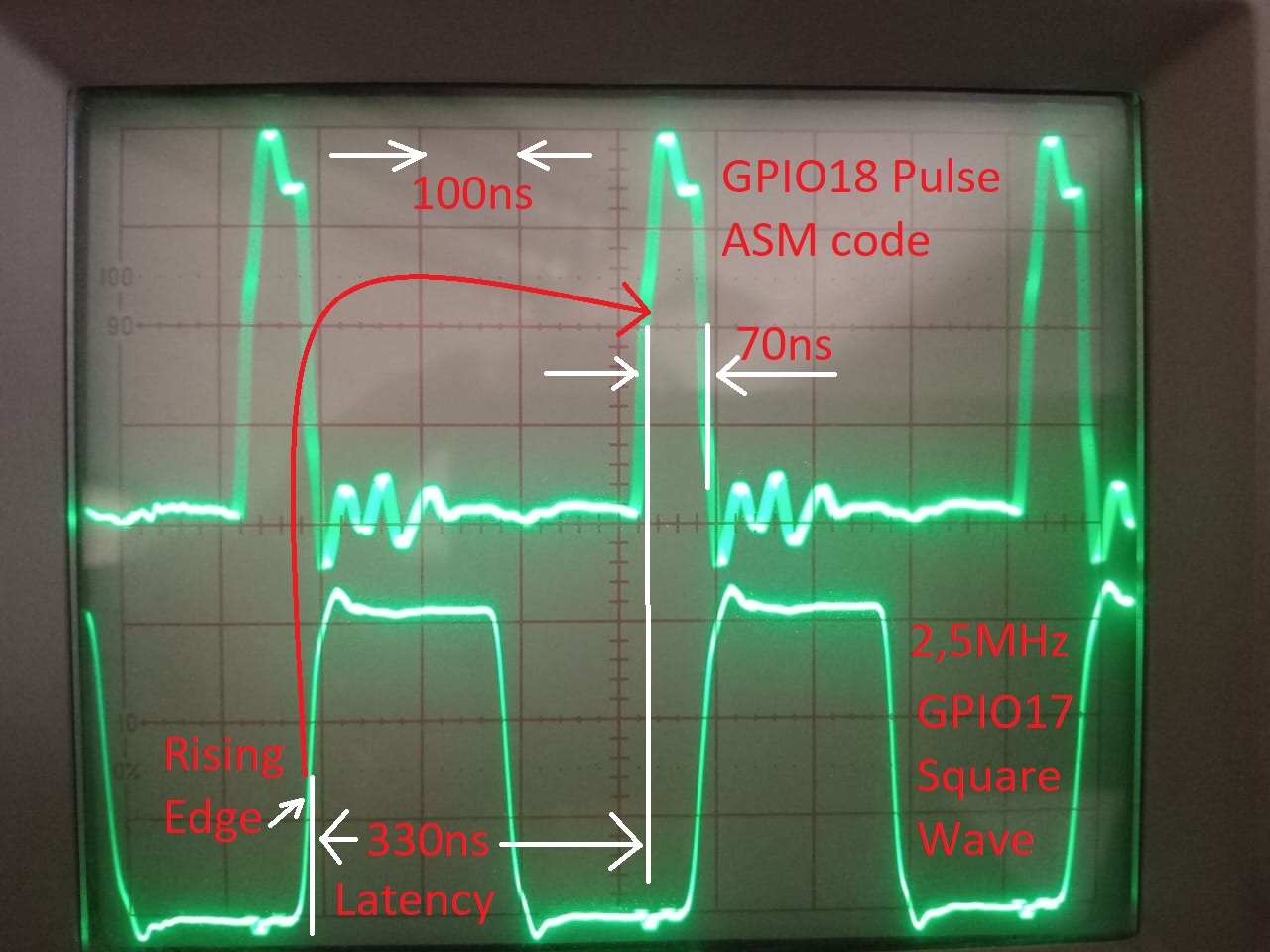
I am feeding a square wave on GPIO17 and expecting on the Oscilloscope at least a short pulse on GPIO18.
The code starts printing a lot of stuff (probably a debug level of IDF) and crashes inmediately.
- To my sdkconfig.project name y removed
CONFIG_ESP_TASK_WDT_CHECK_IDLE_TASK_CPU0 and
CONFIG_ESP_TASK_WDT_CHECK_IDLE_TASK_CPU1
as I was getting watchdog crashes too
- On CMakeLists.txt I added
target_link_libraries(${COMPONENT_TARGET} "-u ld_include_xt_highint5")
as I understand, it is important for the linker
I have no clue if platformio.ini requires a flag or something else to produce an executable that behaves different or if there is a bug in the code or if I introduced a bug.
Any help or clue would be appreciated!