Hello,
I just got an ESP-EYE devkit. I would like to know which board I should use to be able to use the camera? Or which lib.
Thanks,
Corentin
Hello,
I just got an ESP-EYE devkit. I would like to know which board I should use to be able to use the camera? Or which lib.
Thanks,
Corentin
it looks like the board has just been added to the arduino-esp32 repo. Just have to be patient and wait a bit.
Hi!
You can use this board config:
[env:esp32dev]
board = esp32dev
platform = espressif32
framework = arduino
board_build.partitions = huge_app.csv
Arduino core for ESP32 comes with an example CameraWebServer.ino which you can use for basis. The board_build.partition setting is there because for this example, it would not otherwise fit.
Be prepared to be patient though, it’s quite a fiddly board unfortunately. I was able to get the example working for most parts but the face tracking always crashed my board. Based on what I read, the camera would work better on ESP32 WROVER based board with it’s added PSRAM. ESP-EYE is based on a regular WROOM module.
Then there’s Micro-RTSP library for example: GitHub - geeksville/Micro-RTSP: A RTSP video server intended for very small CPUs (ESP32 etc)
The developer has a popular example project TenDollarWebcam in another repository: GitHub - geeksville/TenDollarWebcam: A small example app for ESP32 + Micro-RTSP
I did not get that working though but I’m starting to think there might be some issue with my ESP-EYE as many people seem to have got it working, otherwise the repository would not have 137 stars.
I hope this helps. This is as far as I got with it the last time I had time to play around with it.
@Macfly I just noticed your two messages are talkng about two separate boards which got me confused. ESP-EYE is a development board made by Espressif themselves: ESP-EYE AI Board I Espressif
It seems to include the added PSRAM.
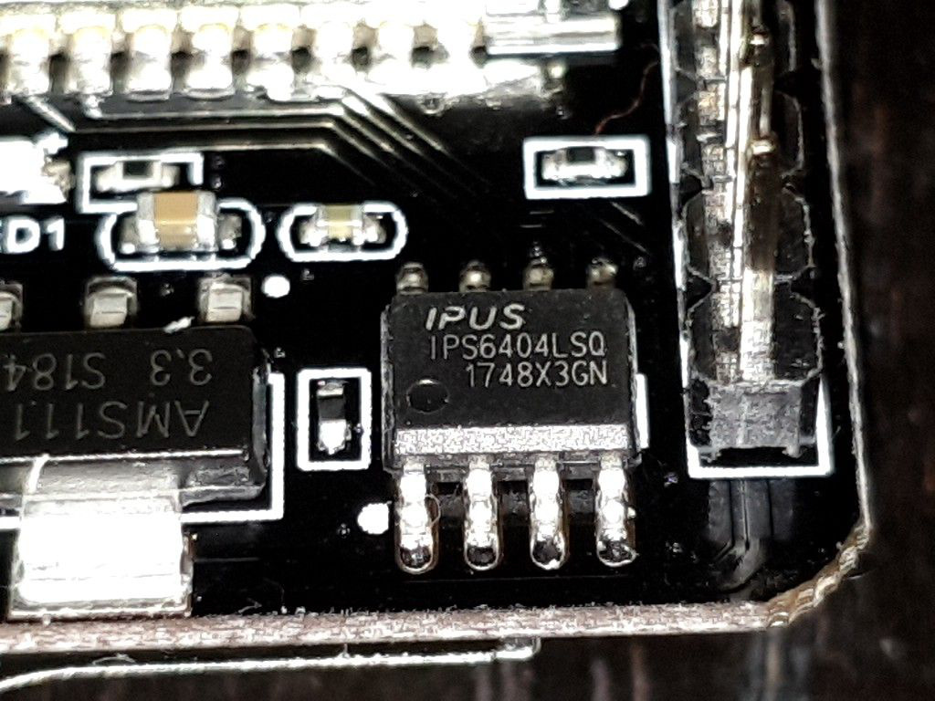
My comment was about ESP32-CAM which is a different board that’s commonly sold on AliExpress. When writing my previous comment I was in the belief it does not have PSRAM onboard but I was mistaken. It has an Ipus IPS6404LSQ 8MB PSRAM chip:
Enabling PSRAM with PlatformIO is documented here: Espressif 32 — PlatformIO latest documentation
Arduino
[env:myenv]
platform = espressif32
framework = arduino
board = ...
build_flags =
    -DBOARD_HAS_PSRAM
    -mfix-esp32-psram-cache-issue
ESP-IDF
[env:myenv]
platform = espressif32
framework = espidf
board = ...
build_flags =
    -DCONFIG_SPIRAM_CACHE_WORKAROUND
I think I’m going to have to give the board another shot now. ![]()
Commenting here to myself in case someone ends up reading these later. ESP32-CAM board works a lot better now with PSRAM enabled. So combining the two configs I’ve posted earlier it works fine!
We added board = esp32cam board profile with enabled PSRAM by default.
I think there are two different boards with similar features. One is the ESP-CAM and the other is ESP-EYE: https://diyprojects.io/esp32-cam-which-model-choose-esp-eye-aithinker-ttgo-tcamera-m5stack
Is there any experienced user that can add compatibility with the ESP-EYE? As is slightly different I’m not sure if it will work.
Thank you.
In addition, if you are using the MicroRTSP library GitHub - geeksville/Micro-RTSP: A RTSP video server intended for very small CPUs (ESP32 etc) with an ESP-EYE board you will need to create a new camera_config_t.
Edit the following files (Micro-RTSP\src\OV2640.h, Micro-RTSP\src\OV2640.cpp)
1: Micro-RTSP\src\OV2640.h
Line 11: add a new name to camera_config_t e.g.
extern camera_config_t esp_eye_config, esp32cam_config, esp32cam_aithinker_config, esp32cam_ttgo_t_config;
2: Micro-RTSP\src\OV2640.cpp
Create a new camera_config_t definition with the same name and adjust
the pin values to those outlined by expressif arduino-esp32/camera_pins.h at master · espressif/arduino-esp32 · GitHub e.g.
camera_config_t esp_eye_config {
    //from https://github.com/espressif/arduino-esp32/blob/master/libraries/ESP32/examples/Camera/CameraWebServer/camera_pins.h
    .pin_pwdn = -1,     //#define PWDN_GPIO_NUM    -1
    .pin_reset = -1,    //#define RESET_GPIO_NUM   -1
    .pin_xclk = 4,      //#define XCLK_GPIO_NUM    4
    .pin_sscb_sda = 18, //#define SIOD_GPIO_NUM    18
    .pin_sscb_scl = 23, //#define SIOC_GPIO_NUM    23
    .pin_d7 = 36,       //#define Y9_GPIO_NUM      36
    .pin_d6 = 37,       //#define Y8_GPIO_NUM      37
    .pin_d5 = 38,       //#define Y7_GPIO_NUM      38
    .pin_d4 = 39,       //#define Y6_GPIO_NUM      39
    .pin_d3 = 35,       //#define Y5_GPIO_NUM      35
    .pin_d2 = 14,       //#define Y4_GPIO_NUM      14
    .pin_d1 = 13,       //#define Y3_GPIO_NUM      13
    .pin_d0 = 34,       //#define Y2_GPIO_NUM      34
    .pin_vsync = 5,     //#define VSYNC_GPIO_NUM   5
    .pin_href = 27,     //#define HREF_GPIO_NUM    27
    .pin_pclk = 25,     //#define PCLK_GPIO_NUM    25
    .xclk_freq_hz = 20000000,
    .ledc_timer = LEDC_TIMER_0,
    .ledc_channel = LEDC_CHANNEL_0,
    .pixel_format = PIXFORMAT_JPEG,
    // .frame_size = FRAMESIZE_UXGA, // needs 234K of framebuffer space
    // .frame_size = FRAMESIZE_SXGA, // needs 160K for framebuffer
    // .frame_size = FRAMESIZE_XGA, // needs 96K or even smaller FRAMESIZE_SVGA - can work if using only 1 fb
    .frame_size = FRAMESIZE_SVGA,
    .jpeg_quality = 12,               //0-63 lower numbers are higher quality
    .fb_count = 2 // if more than one i2s runs in continous mode.  Use only with jpeg
};
NOTE: the pin names are not exactly 1:1 but easy enough to translate by looking at the other examples e.g. compare the camera config for aithinker in the OV2640.cpp vs expressif’s camera_pins.h