I am currently learning/working with EEPROM’s and I find myself asking this question:
When I write the device address with the control code, do I use a hex A (1010) or 5 (0101)?
This might be a silly question, but, it causes me a fair amount of confusion as I have come across examples using 0x50 or `0xA0’ when writing the device address. Does it perhaps have to do with what Endian system the chip uses?
If anyone feels so inclined (pretty please) to provide an explanation I would be truly grateful, and might be able to finally get some sleep!
In the I2C world, everything has an address. This will be a 7 bit address, note seven. When reading from an I2C device with the 7 bit address 0x49, it is converted to an 8 bit read address by shifting the 7 bit address leftwards by 1 bit (multiply by two) then sticking a 1 bit into the now vacant bit 0 position. This gives an 8 bit read address of 0x93.
When writing, on the other hand, the 7 bit address is shifted leftwards as before, and a 0 shoved on the end. Our device with the 7 bit address of 0x49 becomes 0x92.
So, the same device has two separate 8 bit I2C addresses, a read address of 0x93 and a write address of 0x92. Easy!
Your I2C EEPROM has a 7 bit address of 0x50 which means it has a write address of (0x50 * 2) and a read address of (0x50 * 2 + 1), or, a read address of 0xA1 and a write address of 0xA0.
So, when you see examples using 0x50 that’s the 7 bit device address. When it’s 0xA0 that is the 8 bit write address and if you see 0xA1, that’s the 8 bit read address.
Most, but not all I2C code I’ve come across takes the 7 bit address and manipulates it internally to give the appropriate read or write address as required.
Thank you @normandunbar for that amazing explanation!!!
I have been wracking my brain wondering if using either 0x50 or 0xA0 would cause any sort of issues.
During my nth readthrough of the datasheet last night, I took note of the Start
Bit during the various write and read sequences, and was beginning to wonder if that was where my secret zero was coming from, and therefore (in my head) justified the 0x50 and 0x51 read and write addresses respectively.
Do you find that it is safer to use the 8-bit address over the 7-bit address when writing your code? Or does it truly not matter? Personally I find the 0xA0 and 0xA1 more visually appealing
I apologize for the additional questions. I do have a tendency to make things more complicated for myself than need be…
When I write code for TWI/I2C, I usually try to work with the 7 bit address, and adjust it as desired in my read and write code. This way, the user of my code only has to remember a single address and can pass that around willy-nilly.
The 0x49 example I used was taken from some code I wrote (for my second Arduino book) to access an I2C temperature sensor. It’s configured as address 0x49 and the code does the rest for reading and writing. I’m too old to try and remember two addresses for everything!
If you wish, you can do this in your code and get the best of both worlds:
const int LM75A_ADDRESS = 0x49;
const int LM75A_READ_ADDRESS = (((LM75A_ADDRESS) << 1) | 1);
const int LM75A_WRITE_ADDRESS = (((LM75A_ADDRESS) << 1) | 0);
Then you can use LM75A_READ_ADDRESS and LM75A_WRITE_ADDRESS whenever the 8 bit address is required.
@normandunbar fantastic!! I very much appreciate your insight whilst I begin my introduction to the I2C world!
I don’t suppose you might humor me and allow me to ask one final question (I promise)…
During the reading and writing process to I2C, we have to provide the MSB and LSB for the given address, which (in the code I’ve reviewed) is written as follows:
...
int msb = (int)(address >> 8);
int lsb = (int)(address & 0xff);
...
Throughout my testing(and general curiosity) I’ve found that the MSB (at least from 0 - 255) is always 0 and the LSB is the value of the address itself (which seems to be the case regardless):
What confuses me is that if the MSB is the number on the furthest left, for example, 148 in binary is 10010100 and therefore its MSB would be 1. But, when I use the shift right operator, the MSB = 0 and not 1, which is another thing I can’t seem to wrap my head around just yet…
I don’t suppose you might have some insight as to why this is?
I know this slightly relates to my initial question, and if I need to create a new thread for discussion, I am more than happy to
I wonder if you are a tad confused between Most/least significant byte and bit?
If your EEPROM addresses are 16 bit wide, then that’s two bytes. For example, the address 0x1234 has two bytes, 0x12 and 0x34.
The former is the MSB and the latter the LSB. I suspect you are needing to communicate with the EEPROM to tell it what address to write to? And because the EEPROM only has an 8 bit data bus, you have to supply the address as two separate bytes.
So, to get the LSB all you have to do is mask out the upper/MSB byte with address & Ox00ff.
To get the MSB you need to shift the address 8 bits rightwards, hence address >> 8.
Feel free to ask questions if there’s something you need to know.
Haha!! And so I was! Oh, geez…what a humble feeling. Thank you again, @normandunbar!
And just when I thought I wouldn’t have any further questions…here comes another.
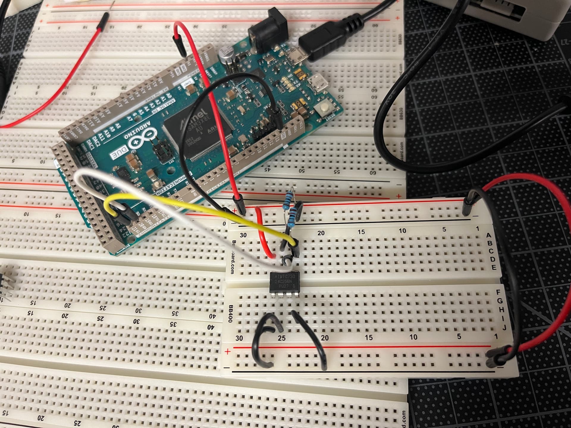
As I mentioned in an earlier message, I am attempting to write to an ATMTC730 24C256N EEPROM. And I am having everything but good luck at attempting to do so. I’ve tried using the individual read-and-write addresses, sending both the MSB & LSB, not sending the LSB, etc.
Below is the code, serial output, as well as my wiring setup.
I am curious as to what your thoughts are on if I am doing everything correctly in my code setup, and wiring.
I did find that I was referencing the datasheet for the C256B which has address pins A0-A2 while my unit, at least the one I think I’m using, only has address pins A0-A1. Does the two-pin setup require some adjustments in my approach?
--- Terminal on /dev/cu.usbmodem14101 | 9600 8-N-1
--- Available filters and text transformations: colorize, debug, default, direct, hexlify, log2file, nocontrol, printable, send_on_enter,
time
--- More details at https://bit.ly/pio-monitor-filters
--- Quit: Ctrl+C | Menu: Ctrl+T | Help: Ctrl+T followed by Ctrl+H
FFFFFFFF
FFFFFFFF
FFFFFFFF
FFFFFFFF
FFFFFFFF
Hey, no worries, we all make mistakes sometimes! (Said the hedgehog, climbing off the toilet brush! It doesn’t help that the data sheet shows LSB and MSB in the timing diagrams for Most/Least significant bit though! I use “high byte” and “low byte” to avoid misunderstandings.
I downloaded the linked data sheet, thanks, and I’ve had a look see.
Those address bits, either 3 or 2, are just there to allow multiple devices on the I2C bus. Each device must have a unique 7 bit address, so that each can be individually addressed. If you had two devices with the same address then there would be corruption, at best!
By default, you should wire those two lines, A0 and A1, to ground to ensure that they are indeed at ground potential. The data sheet says that if the capacitance of the circuit is < 3PF, they can be left floating, but how can we hobbiests measure this? Just wire them.
Hey! I’m only pretending to know what I’m typing! I had similar difficulties when I first had to look into I2C, so there is no problem in being confused to start with. My advice, take notes!
I see from the image, thanks, that you have the address pins hard wired to ground, this is good, and gives you a 7 bit address of 0x50.
From Figure 8, page 11, it appears that the EEPROM memory address you want o write to is sent in high byte then low byte format. Each byte returns an ACK (acknowledgement) from the EEPROM.
From BYTE WRITE, page 10, After the ACK for the low byte of the address, you send the data byte to be written there, wait for the ACK, and then stop the communication. At this point, the data will be clocked into the EEPROM cell.
You appear to have the beginTransmission() call outside the loop, for a single byte write to “random” addresses, you need to start and stop the transmission for each byte bytes.
I think you really need to do a PAGE WRITE instead, as you are writing to incrementing addresses.
    Wire.beginTransmission(ADDRESS); // NOTE, outside the loop.

    Wire.write((int)(address >> 8)); // NOTE, outside the loop.
    Wire.write((int)(address & 0xff)); // NOTE, outside the loop.

    for (int address = 0; address < 5; address++) {
        Wire.write(0xAA);
    }

    Wire.endTransmission(); // NOTE, Outside the loop, also!
In this mode, you start the transmission, send the address high byte, the low byte, then enter a loop where up to 64 data bytes can be sent. When you have sent as much data as you need, you exit the loop and end the transmission.
After this, the EEPROM will do it’s thing internally. You can wait for it to complete by:
Sending a start condition.
Send the EEPROM’s read address. (or the write, if you have more data to write).
Send a STOP condition. Assuming you don;t actually wish to read or write more data!
The EEPROM will respond to its own address when it has finished doing the necessary for the bytes you just wrote.
Beware of setting an address to write to, then sending too many bytes. Once you hit the end of a page, the EEPROM will start writing at the beginning of the same page, overwriting data you may not want overwriting! Pages are 64 bytes in size. This means that the lowest 6 bits of the EEPROM data address will be incremented for each data byte received, and when they rollover to all zeros, you are now potentially corrupting data in the EEPROM if you keep sending data.
When reading data back from this EEPROM, you can set up a random read:
@normandunbar, what a pleasant and in-depth response! Thank you so much for taking the time to deep dive with me on this I2C adventure! I cannot express how much it means to me!
After taking some time to understand the process for reading and writing to the device, as well as making the suggested edits to my code (see below), I am still getting -1 or FFFFFFFF response from the Serial output (see below). My understanding (from the reading I’ve done) is that the either device address I’m requesting from does not exist, or some other error.
I am at a complete loss now. I was hoping for a stroke of dumb luck to strike me and give me the glorious data I’ve been seeking all week…but, alas, I still dream.
I have gone so far as to hardcode the address I would like to read and write from. Still no luck.
I’ve tried using other 24C256 units, and even other boards with the same results (but at least I’m consistent).
#include <Arduino.h>
#include <Wire.h>

#define EEPROM_ADDR_W 0xA0
#define EEPROM_ADDR_R 0xA1

int max_bytes = 5;

void setup() {
    Wire.begin();
    Wire.setClock(100000);

    delay(100);

    Serial.begin(9600);
    Serial.println();

    Wire.beginTransmission(EEPROM_ADDR_W);
    Wire.write((int)(0x01 >> 8));
    Wire.write((int)(0x04 & 0xff));

    for (int i = 0; i < max_bytes; i++) {
        Wire.write(byte(i));
    }

    Serial.print(Wire.endTransmission(true));
    Serial.println();

    delay(2000);

    for (int i = 0; i < max_bytes; i++) {
        Wire.beginTransmission(EEPROM_ADDR_R);
        Wire.write((int)(i >> 8));
        Wire.write((int)(i & 0xff));
        Serial.print(Wire.read());
        Wire.endTransmission();

    }
}

void loop() {}
Serial Output
--- Terminal on /dev/cu.usbmodem14201 | 9600 8-N-1
--- Available filters and text transformations: colorize, debug, default, direct, hexlify, log2fi
le, nocontrol, printable, send_on_enter, time
--- More details at https://bit.ly/pio-monitor-filters
--- Quit: Ctrl+C | Menu: Ctrl+T | Help: Ctrl+T followed by Ctrl+H

2
-1-1-1-1-1
@normandunbar, we’ve done it!! Or at the very least we finally have SOMETHING!
For starters I ditched using both the read and write addresses, as like you said, the methods do the work for you, i.e. beginTransmission starts the write process, and requestFrom initiates the read process. At least those are my thoughts currently.
The other bit took some further reading up on the device’s supposed read and write processes. In my current code (see below) I am doing a dynamic Byte Write of sorts, which involves the usual Device Address + First Word Address + Second Word Address and then writing data and finally passing the stop command bit with endTransmission.
With reading the data I am (from what I gather) either using the Current Address Read or Sequential Address Read process (still haven’t figured out which one as of yet). In that, I am essentially requesting the previous 10 bits of data from the last known accessed address.
Current Code
#include <Arduino.h>
#include <Wire.h>

#define EEPROM_ADDR 0x50

int total_bytes = 10;

void setup() {
    Wire.begin();

    delay(100);

    Serial.begin(9600);

    Serial.println();
    Serial.println("=== Begin Write ===");

    Wire.beginTransmission(EEPROM_ADDR);

    int t = 0;
    for (int d = 0; d < total_bytes; d++) {
        Wire.write((int)(d >> 8));
        Wire.write((int)(d & 0xff));
        Serial.print(d);
        Serial.print(" -- Write value: ");
        Serial.print(d, HEX);
        Serial.print(" -- Status: ");
        Serial.println(Wire.write(d+1));
        t++;
    }

    Serial.print("Bytes written: ");
    Serial.println(t);

    Serial.print("Status: ");
    Serial.println(Wire.endTransmission());

    Serial.println("=== End Write ===");
    Serial.println();

    delay(500);

    Serial.println("=== Begin Read ===");

    Serial.print("Bytes retrieved: ");
    Serial.println(Wire.requestFrom(EEPROM_ADDR, total_bytes));

    if (Wire.available() < 0) {
        Serial.print("Error");
        Serial.println();
    }

    if (Wire.available()) {
        while (Wire.available()) {
            Serial.println(Wire.read(), HEX);
        }
    }

    Serial.print("Status: ");
    Serial.println(Wire.endTransmission());

    Serial.println("=== End Read ===");
}

void loop() {}
I have to say that I was quite relieved and ecstatic when I finally saw something worthwhile come through the serial monitor. There is still quite a bit more to figure out. My main focus is to figure out the Random Read process as it involves the unique dummy write setup before requesting data. That sounds like fun…
Thank you for persisting through this with me! I don’t think I would’ve stuck through it to this point without you!
You do realise you wrote the values 1 through 10 (you wrote d+1) rather than 0 through 9?
Yes, you are doing random writes and sequential reads. You can also do sequential writes, just set the address outside the loop and write the data in the loop, then end transmission after the loop. I gave you an example in a previous post.
Still, you are making progress.
Maybe try out the write example I’ve linked above, see what happens?