I have wired up a Digispark Kickstart ATTiny85 board (looks like a Digistump), an OLED display and two DS180B20 sensors. If I supply power to all units but disconnect the sensor bus from the board it connects when I plug in the USB plug to the PC. If the sensor lead is connected the board will not connect at all. Is there a lack of power or what?
Maybe you’ve plugged one of the data pins into the pins that are used for USB? What are the exact connections?
I’ve been able to upload the sketch when I had the sensors unplugged, sensor wire to pin P3 which is defined in the source. If I plug in the USB to supply power and have the sensors disconnected the display comes on and shows temp -127 and -256 since the sensors are out. If I then connect the sensors it changes to 25 and 25 so the wiring seems correct. If I have the sensors connected when I plug in the USB nothing happens. It looks like it doesn’t get enough power for all units.
I was going to make a Fritzing drawing of it but I couldn’t find a part for the Digistump.
Evening Hans.
There is a digispark part in the temp parts bin in the .fzz file for this project:
http://fritzing.org/projects/xmas-candle-project-diy
The actual project download is here. (I would have put the URL but it’s on Amazon AWS so is long long long!)
Cheers,
Norm.
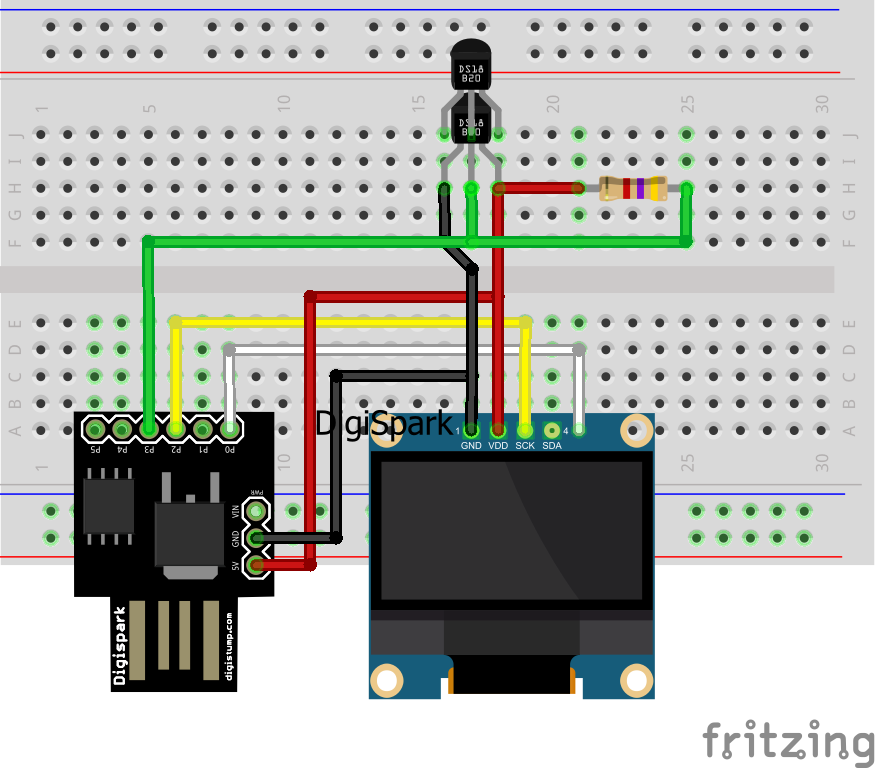
P2 and P3 are the USB D+ and D- lines per schematic. These have specific pull-up and series resistors on them, especially P3 with 1.5kOhm to +5V. And on P3, you have another pullup resistor to VDD, thus alterting the total resistance according to the parallel resistance formula. This probably screws with the USB bus enough to make the device unrecognizable.
Try and move the data pin of the sensors away from P3. Or, leave it there, but disconnect the sensors before every programming cycle to be able to program them.
1 Like