I need a dev board recommendation. I’m trying to finish up a project that has an array of sensors: two flow meters, two solenoids, a temperature probe, a thermometer and humidity sensor, three pressure sensors, and a I2C LED display.
The solenoids require 12V, so opening and closing them is done through a relay. Which means, I have two output pin requirements. The pressure sensors are 5V analog. So I have a breakout ADC running through I2C with the LED. I also have two buttons, that need to be run through an interrupt.
So I have, at the end, needs for:
SCL/SDA
6 additional input pins, 4 of which need EXTI (the flow meters and buttons)
2 output pins
Pins need to be 5V tolerant
So, depending on the board, 10 usable GPIO pins
I went through what I’ve got laying around the house:
Nano (ATmega328) and Uno -> Out because only 2 pins for interrupt
Pro Micro -> Out because 2 of the 5 interrupt pins are SCL/SDA, needed for I2C
NodeMCU 8266 -> Out because only really 9 GPIO pins, and I need 10… and of the 9, it seems half boot HIGH
Particle Argon -> Would work, but kinda pricey, and don’t want to burn it up testing
So I’m looking for something, preferably on the cheaper side (than a particle), since this is just prototype, that I can burn up and not be sad. If none exists, I’ll just use the particle.
Anyone got a recommendation? A Nano 33 would probably work, but it shipped is about the same price as the argon, and I don’t have to wait for the argon to ship, as its already here.
Looks like STM32 “Blue Pill” is going to work, based on just a brief glance. If anyone knows otherwise, just post here, and then I’ll just have some spare blue pills, but I’m going to order a few.
It should work with a Blue Pill if your I2C bus can run with 3.3V as the Blue Pill uses 3.3V. Also take care that not all pins are 5V tolerant.
Don’t forget to order an ST-Link v2 debug probe as you usually cannot upload the firmware via the USB port. The ST-Link will allow you to use the debugger, a big big plus!
Thanks. I’ve got a probe, but definitely glad I do, otherwise…
Looking at a pinout, I think I’ve got a enough 5V tolerant pins to do what I need, and the I2C bus should run 3V3.
I think the only reason I’ve got a 5V power supply is for the pressure sensors, so I might just run everything 3V3 and branch off a 5V for just the pressure sensors, then I don’t need the 5V tolerance anymore.
I’m gonna try it. Should work. This board looks really neat.
Why use an external A/D? That seems like more parts that you don’t need.
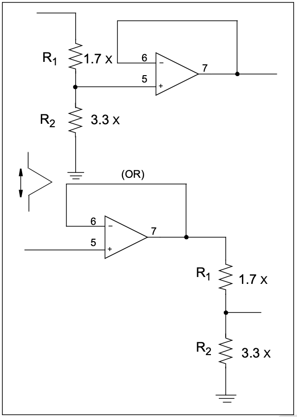
I would recommend using a simple op-amp like an OPA336 with a Vcc the same as the microprocessor (3.3 VDC?) and a resistor network to drop the 5 VDC sensor output to 3.3 VDC. The OPA336 with a Vcc of 3.3 VDC will insure you never over-voltage the micro’s A/D.
Not necessarily… there are only two dedicated interrupts, but depending on the application, you can also use pinchange interrupts meaning any of the pins can be be used as a quasi interrupt pin. However, the STM32 is a really good choice due to it being faster, having more memory, and having more IO whilst still being ridiculously cheap.
We need the full range of the sensor, 0-5V. Scaling it to 0-3.3 loses a large amount of the resolution of the sensor, since the sensors are linear analog.
How so? If your A/D has a maximum voltage span of 0 to 3.3VDC and say 12 bits of resolutions, then every count is still 0.0244% of the total span (1 part of 4096).
The same goes for 0 to 5 VDC span.
All you are doing is shrinking or rescaling the span, not changing the number of A/D steps from minimum to maximum. In other words, 2.5 VDC from the sensor becomes 1.65 VDC. 3 VDC becomes 1.98 VDC.
There are two ways to do a level-shift with an op-amp. First, the op-amp power supply should be at 3.3 VDC (same as the microprocessor). Then you can rescale the output from a 5VDC device to a 3.3 VDC device using a pair of resistors as a voltage divider and a unity-gain op-amp.
Thanks, the stm32 ended up having a steeper learning curve than I have time to trek at the moment, so I’m going to try pinchange interrupts on the nano.
I flashed the stm32 bootloader, and it was seen in windows as a COM device, but flashing using dfu through PIO errored. And I also couldn’t flash it via STLINK, so… I’ll figure that out another day, and just try the PCINTs, thanks!