Debugging WEMOS D1 Mini ESP8266 via JTAG

Hi,
I’m new to PlatformIO and ESP Processors, but doing embedded software on various platforms for many years.

However, this drives me crazy :frowning_face:

I started with a simple LED blinker, uploaded it via USB, works fine.
I learned, that debugging is not possible via USB - only JTAG. I also found that I can use the FT232H.
Fine, I still have a Digilent HS3 for my FPGA-Boards, which is pretty much the same.
I checked the USB-IDs with FT_Prog - fine. The plain FTDI driver is installed.

This is my config:

[env:d1_mini_debug]
platform = espressif8266
board = d1_mini_lite
upload_protocol = esp-prog
debug_tool = esp-prog
debug_init_break = tbreak setup

Starting a debug session just stops after the build, no error message.
I found that I can set “debug_tool = Grbage4711” and it would do the same.
Then I added the upload-protocol and tried upload. I got the warning “Warning! Unknown upload protocol esp-prog”.

Now I’m really frustrated. I don’t find any troubleshooting and the tool doesn’t tell me what’s wrong :frowning:

ESP8266 chips have no hardware debugging support in PlatformIO. Only ESP32 has that. See

Historically there have been issues with that and Espressif does not seem to support this well, as the only JTAG reference I see in Espressif docs are how to disable it. Even the linked post says they had to fixup sysprogs/esp8266-openocd to get that working, in rsaxvc/sysprogs-esp8266-openocd.

Have you tried getting a connection to the ESP8266 via that special OpenOCD version on the commandline?

I forked into https://github.com/maxgerhardt/sysprogs-esp8266-openocd since there were some compiler errors for me. Now I do have that OpenOCD version compiled. I uploaded (regularly) this sketch to my NodeMCUv2 as is recommended by that blog post:

#include <Arduino.h>

void setup() {
    pinMode(12,FUNCTION_0);//TDI
    pinMode(13,FUNCTION_0);//TCK
    pinMode(14,FUNCTION_0);//TMS
    pinMode(15,FUNCTION_0);//TDO    
}

void loop() {
    delay(1000);
}

I then hooked up my Adafruit FT232H Breakout board to my NodeMCU board using the pinout and mapping

  • ADBUS0 (“D0”, TCK) to GPIO13
  • ADBUS1 (“D1”, TDI) to GPIO12
  • ADBUS2 (“D2”, TDO) to GPIO15
  • ADBUS3 (“D3”, TMS) to GPIO14

and using

./bin/openocd -s share/openocd/scripts/ -f interface/ftdi/c232hm.cfg -f target/esp8266.cfg

It actually manages to get a connection to the chip!

Open On-Chip Debugger 0.10.0+dev-g63d9b121 (2023-11-05-15:10)
Licensed under GNU GPL v2
For bug reports, read
	http://openocd.org/doc/doxygen/bugs.html
stop_wdt
Info : Listening on port 6666 for tcl connections
Info : Listening on port 4444 for telnet connections
Info : clock speed 1000 kHz
Info : TAP esp8266.cpu does not have valid IDCODE (idcode=0xfffffffe)
Info : halted: PC: 0x40000f68
Info : debug cause: 0x20
Info : Listening on port 3333 for gdb connections
$ telnet 127.0.0.1 4444
Trying 127.0.0.1...
Connected to 127.0.0.1.
Escape character is '^]'.
Open On-Chip Debugger
> halt 1000
> reg 
===== Xtensa registers
(0) a0 (/32): 0x60000900 (dirty)
(1) a1 (/32): 0x00000000 (dirty)
(2) a2 (/32): 0x00000000
(3) a3 (/32): 0x00000020
(4) a4 (/32): 0x00000000
(5) a5 (/32): 0x00000002
(6) a6 (/32): 0x4020E61C
..

But xtensa-lx106-elf-gdb just crashes when trying to connect to the GDB server (127.0.0.1:3333), not sure why yet…

Using the official toolchain from https://docs.espressif.com/projects/esp8266-rtos-sdk/en/latest/get-started/linux-setup.html instead of the PIO toolchain-xtensa package and installing libpython2.7 on Ubuntu 22.10 (which was a pain) to make GDB runnable actually gave a working connection…

(gdb) target remote :3333
Remote debugging using :3333
warning: No executable has been specified and target does not support
determining executable automatically.  Try using the "file" command.
0x40000f68 in ?? ()
(gdb) x/10i $Pc
Value can't be converted to integer.
(gdb) x/10i $pc
=> 0x40000f68:	call0	0x40000f80
   0x40000f6b:	j	0x40000f4f
   0x40000f6e:	sub	a0, a0, a0
   0x40000f71:	bnez.n	a15, 0x40000f94
   0x40000f73:	.byte 0x3f
   0x40000f74:	rsil	a2, 3
   0x40000f77:	l32r	a3, 0x40000f70
   0x40000f7a:	s32i.n	a2, a3, 0
   0x40000f7c:	ret.n
   0x40000f7e:	or	a0, a0, a0
Installing Python2.7 on Ubuntu 22.10
wget http://launchpadlibrarian.net/623026710/libpython2.7-minimal_2.7.18-13ubuntu2_amd64.deb
wget http://launchpadlibrarian.net/623026713/libpython2.7_2.7.18-13ubuntu2_amd64.deb
wget http://launchpadlibrarian.net/623026711/libpython2.7-stdlib_2.7.18-13ubuntu2_amd64.deb

sudo dpkg -i libpython2.7-minimal_2.7.18-13ubuntu2_amd64.deb 
sudo dpkg -i libpython2.7-stdlib_2.7.18-13ubuntu2_amd64.deb 
sudo dpkg -i libpython2.7_2.7.18-13ubuntu2_amd64.de

Okay the reset is problematic. When I disable the reset (“attach to running target”) and do some other shenanigans inspired by https://github.com/esp8266/Arduino/blob/master/libraries/GDBStub/gdbcmds it starts working…

Let’s see why it can’t properly reset…

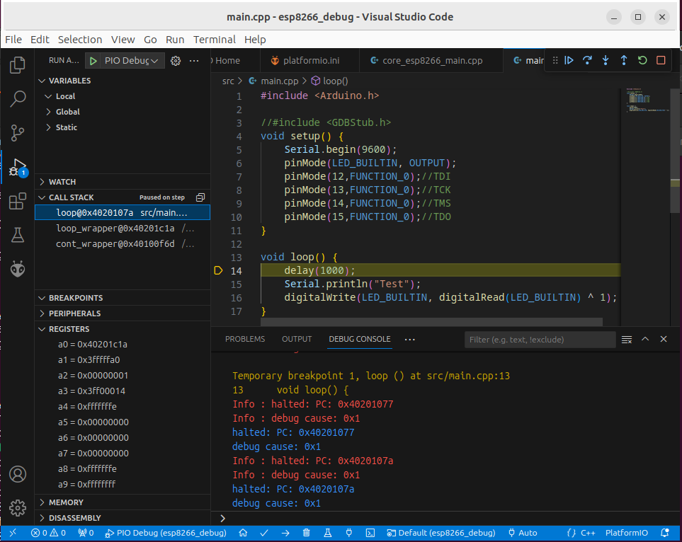
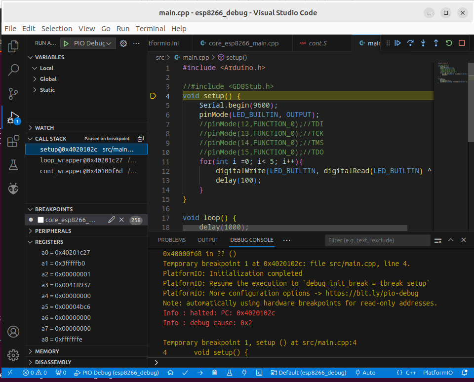
The reset problem was due to incorrect OpenOCD adapter configurations and I was able to resolve it. It can now reset the chip via OpenOCD. The problem is however that there is no “reset but don’t start running code”. There is only “reset and try to halt execution ASAP afterwards”. But at that point, init code and setup() has already run, so setup() can’t be initial breakpoint anymore, only loop, after it has done a few iterations… Not yet sure how to handle this well. One way good to delay() for debugger connection before in setup() in the core for a debugger connection, then this works.

In any case, this is not production ready yet and I doubt that’ll change in the short term. Even if I get it running, getting it all stable and accepted back into mainline will take its time.

Thank you @maxgerhardt for your quick and detailed reply.
I’ll try your suggestions when I have time.

I was hoping to put my efforts in my task and not in the toolchain.
Right now, I help myself with UART monitor and logic analyzer.
I have also problems getting reliable hardware docs.
I think, I’ll focus on my other projects and keep this one as
“weekend hobby”.