PlatformIO: Initializing remote target...
.pioinit:13: Error in sourced command file:
:3333: The system tried to join a drive to a directory on a joined drive.
Does anybody know what is the problem here?
If you need any more information just let me know. I do not really know what is helpful in solving this case since I do not know much about these things and am complete beginner. Any help is greatly appreciated.
Running a piece of code on a Leonardo (as declared in your platformio.ini) does not require debugging to work – PlatformIO has very limited AVR debugging capabilities anyway. Are you sure you’re using the project task “Upload” (while having used the project environment switcher to select the correct project + environment), or do you really want to debug the firmware with line-by-line debugging?
Thanks for the reply. I am running it on Arduino UNO but I think that I have set up everything as it is supposed to be. The code can be uploaded to the Arduino but the AT commands are written as a plain text and are not returning any values.
Yes but I changed Serial1 to only Serial since that is how it should communicate. But since I am complete beginner I do not know if have to messed up somewhere
Can you run this piece of code on the Uno (while the shield is connected of course)
#include <Arduino.h>
#include <serialcmds.h>
#include <narrowbandcore.h>

// Select serial object for modem communication
// Please look at the specs of your board and locate
// the Serial object with a pin mapping compatible to
// the shield you're using.
HardwareSerial& modem_serial = Serial;      // Serial1

#define DC_DC_ENABLE A0 	/* A0 */
#define RESET_N 13 			/* D13 (unused here) */

void setup() {
    // Begin modem serial communication with correct speed (check shield specs!)
    // TEKMODUL BC68-DEVKIT         9600,echo
    modem_serial.begin(9600);

	//try with LOW or HIGH or without this code,
	pinMode(DC_DC_ENABLE, OUTPUT);
	digitalWrite(DC_DC_ENABLE, HIGH);

    delay(3000);

    // Instantiate command adapter as the connection via serial
    Narrowband::ArduinoSerialCommandAdapter ca(modem_serial);

    // Driver class
    Narrowband::NarrowbandCore nbc(ca);
	// trigger sending of AT commands, observe raw AT commands on output
    nbc.getModuleInfo();

    nbc.getIMEI();

    nbc.getIMSI();
}


void loop() {
}
And make sure that per manual page 22 the lower left switch is set the “Main UART to MCU” position.
Then upload & monitor that code (with monitor_speed = 9600 in platformio.ini).
I have to try it tomorrow when I am at school but thank you for all the responses. By the way how exactly is the switch working? I have in to UART TO USB right now because I could not upload any code to the module when the switch was on UART TO MCU.
Uploading to the Uno happens via the serial (UART) bootloader on the D0 + D1 pins. The BC68 shield also communicates with the Uno via UART and the exact D0 + D1 pins. So you have a pin conflict – when you want to upload a new firmware to the Uno, the switch must be flipped to the ‘UART to USB’ position so that the BC68 module does not occupy D0 + D1, but in order for the Uno to then be able to communicate with the BC68 at all, it must be flipped back to the ‘UART to MCU’ position after uploading.
That’s why the recommended development board in the user manual linked above is exactly not an Arduino Uno but an ST Nucleo L476RG board. An uno very unsuited for this since you by default only have 1 serial but the wanted usages is programming new firmware + debug outout + communicating with the BC68 module, which ideally happens over three different serial connections (while the first one may also happen in an entirely different way). With a Nucleo board (any Nucleo board, really), the programming happens via SWD (completely different pins and method as opposed to UART), the default Serial is not on D0 + D1, meaning it does not by-default conflict with the BC68 communication UART, and it has tons (as in, 5) Serial peripherals available, one also on D0 + D1, where the module can connect.
I would heavily suggest that you either exchange your Uno for any ST Nucleo board (e.g., F103RB, L47RG, …) as that gives you a much better experience regarding the serial connections and uploading and out-of-the-box working debugging. If it has to be an Uno, the best you can do is using a SoftwareSerial to implement the debug output. (You must use the hardware UART on D0 + D1 for the module communication as that is what the shield is hardwired for).
There are two more tests that you can do:
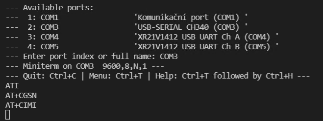
Direct connection: Unplug the BC68 shield from the Uno, flip the switch to “Main MCU to USB” and plug in the right USB cable into the USB port which is located on the shield. It should power it on and you should be able to start a serial monitor at 9600 baud and line-ending = CR+NL and type in AT commands, like ATI, directly to verify that the module is alive. No Uno needed at all for this.
You can turn the Uno into serial-pass through device that accepts serial input (e.g. from an extra USB-UART adapter and a SoftwareSerial) and passes that through to the hardware serial connection on D0 + D1 (where the BC68 is connected to when the shield is plugged in). See this sketch. This would allow you to send AT commands to the Uno via the external USB-UART adapter which in turn outputs it on D0+D1 to the module, which hopefully responds, the Uno can read in that answer and re-output it on the software serial.
The problem is that I have to solve this with Arduino UNO because that is my task. I need this for bachelors thesis and I have been struggling with this a lot so you are helping me a ton and I thank you for that.
#include <Arduino.h>
#include <serialcmds.h>
#include <narrowbandcore.h>

// Select serial object for modem communication
// Please look at the specs of your board and locate
// the Serial object with a pin mapping compatible to
// the shield you're using.
HardwareSerial& modem_serial = Serial;      // Serial1

#define DC_DC_ENABLE A0 	/* A0 */

void setup() {
    // Begin modem serial communication with correct speed (check shield specs!)
    // TEKMODUL BC68-DEVKIT        9600,echo
    modem_serial.begin(9600);
    delay(3000);

    // Instantiate command adapter as the connection via serial
    Narrowband::ArduinoSerialCommandAdapter ca(modem_serial);

    // Driver class
    Narrowband::NarrowbandCore nbc(ca);
	// trigger sending of AT commands, observe raw AT commands on output
    nbc.getModuleInfo();

    nbc.getIMEI();

    nbc.getIMSI();
}


void loop() {
}
At first I have uploaded the code when the switch was to Main UART to USB. Then I switched to Main UART to MCU and tried the monitor and the answer was the same. The AT commands are not translated and are returned as a plain text.
Do I necessarily need the UART to USB thing? Because I feel like I am completely lost and will never be able to finish this task.
My teacher suggested me that I should check if I am using the right pins, protocol or interface for the communication. I will try to search within the BC68 manual for some answers.
Hey. Maybe this is a little late to come for your help.
But the case you and @maxgerhardt describe (Not enough hardware serial connections available to program/debug/run shields), I typically use Software Serial libaries. With these you can use any Hardware pin and run the comms of your shield over them. The limiting factor is load to your microcontroller, but for slower sensor comms that should still be enough.
Furthermore, I propose to rename this thread to something like “hardware serial collisions” or “COM collision” so that other forum users can get a more specific idea.
And, now that some months passed, by curiosity: How did you solve this issue for your Bachelor thesis?
Regards Schallbert