Hi, I designed recently a custom esp8266 with usb-c (used ch340c) that controls multiple triacs and optoisolators. My question is when I try uploading code into the custom pcb the output keep saying Connecting…._…. and in the end it says A fatal error occurred: Failed to connect to ESP8266: Timed out waiting for packet header. The below image is the schematic I hope someone could figure out any missing/wrong connections.
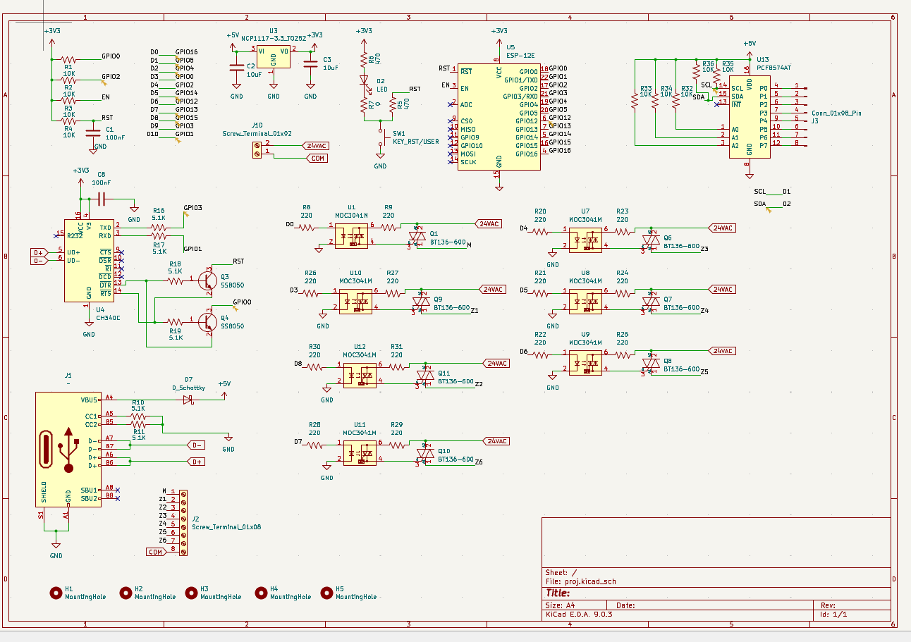
The design has a few weirdnesses.
- the PCF8574 is powered with 5V instead of 3.3V although VCC = 3.3V is fine per datasheet
- SCL and SDA are thus also pulled up to 5V, exceeding the ESP8266’s 3.3V
- the PCF8574’s GPIO pin go completely unused (?), at least with what we see
- I would keep GPIO0 away from anything business-logic related because it’s a boot strap pin to enter bootloader mode (with GPIO0 LOW), but it controls U1
- GPIO15 is another boot strap pin which is documented as “Boot fails if pulled HIGH”, but the pin is not pulled low at all and again controls U12 (source, source)
I would proceed as follows:
- use a standalone serial monitor program like HTerm https://www.der-hammer.info/pages/terminal.html
- open the serial port at 74880 baud (the bootloader’s baud!)
- press SW1. Is there any output at all?
- press the “RTS” button in hterm to make RTS active, then press SW1 again. is there any output? Then deselect the RTS button again.
- press the “DTR” button in hterm to make DTR active, then press SW1 again. is there any output? Then deselect the DTR button again.
- press both the “DTR” and “RTS” button in hterm to make DTR and RTS active, then press SW1 again. is there any output?
1 Like
Thanks for the reply. Sorry for the weirdnesses this is my first schematic design
I tried HTerm but when i press connect it wont connect and says error in openport: Internal error when initializing COMx.
When I try to flash the esp8266 using an arduino ide it get stuck at connecting before it gives a fail message Timed out waiting for packet header). Note that the led on the ESP-12E and led D2 flash during the upload
Edit: When I connected gpio15 to gnd it connected to HTerm and after pressing RTS the output is
 ets Jan  8 2013,rst cause:2, boot mode:(3,6)

load 0x40100000, len 1856, room 16
tail 0
chksum 0x63
load 0x3ffe8000, len 776, room 8
tail 0
chksum 0x02
load 0x3ffe8310, len 552, room 8
tail 0
chksum 0x79
csum 0x79

2nd boot version : 1.5
  SPI Speed      : 40MHz
  SPI Mode       : DIO
  SPI Flash Size & Map: 32Mbit(512KB+512KB)
jump to run user1 @ 1000

rf cal sector: 1017
rf\[112\] : 00
rf\[113\] : 00
rf\[114\] : 01

SDK ver: 1.5.4.1(39cb9a32) compiled @ Jul  1 2016 20:04:35
phy ver: 972, pp ver: 10.1

)<\\f>‚ÐQéP1,ŠYÊY<15>'<3>)§Ã<\\b>)ÍPí<2>ü
SW1 with DTR outputs
<\r><\n> ets Jan 8 2013,rst cause:2, boot mode:(1,7)<\r><\n><\r><\n>
connecting gpio0 to gnd with RTS shows
<\r><\n> ets Jan 8 2013,rst cause:2, boot mode:(1,6)<\r><\n><\r><\n>
Okay, so you have definite signs of life. In fact the first output looks like it definitely tries to jump to a firmware and execute it: Most likely a prebuilt AT+ firmware? You might want to switch the baud rate to 9600 or 115200 and press the SW1 again (without any RTS/DTR set) to see if the last few characters of the output changes to e.g. AT.
Make sure all other serial monitors are closed.
Can you solder a pulldown resistor from GPIO0 (“D3”) to GND and from GPIO15 (“D8”) to GND, and remove resistor R1 then plug the board back in and flash it again? It should definitely flash it when it’s in UART bootloader mode like that.
1 Like
I really appreciate your replies thank you so much. If I remove R1 to flash it do I need to reconnect it after flashing. Also can I use jumping wire without pull down resistors? Again thanks in advance!!
The point of this is just to find out whether your ESP8266 can be flashed at all, that’s why we want to hard-connect GPIO0 to LOW. It’s safer to do that with a pulldown resistor (standard 10K) in case the bootloader or a loaded firmware try to pull this to HIGH. But you can decide whether you want to take the risk.
1 Like
Okay I will try it tomorrow and let you know what will happen!!!
Hello sorry for being late. I did solder a 10k pulldown resistor from GPIO0 and GPIO15 to gnd but still same issue the only difference I see at the output terminal is it gives the error after Connecting…. not Connecting…._…._….
Edit: I desoldered pcf8574AT becuase I thought that there is no enough power for the esp to enter the mode but still same error. Do you think the ch340c should be powered by 5V?
Open a CLI and execute
pio pkg install -g -p tool-esptoolpy
then
pio system info
It should show a line with “Python interpreter”
Python Executable C:\Users\Max\.platformio\penv\Scripts\python.exe
Use that path to construct a command
"C:\Users\Max\.platformio\penv\Scripts\python.exe" "C:\Users\Max\.platformio\packages\tool-esptoolpy\esptool.py" --before no_reset --chip esp8266 flash_id
(Changing both the python.exe path and the esptool.py path appropriately).
What’s the output? Can it read out an ID at all? The board should continously in bootloader mode now with GPIO0 pulled LOW.
Does the subcommand
--before no_reset --chip esp8266 erase_flash
succeed?
1 Like
Both commands gave the same error:
Connecting…
COM3 failed to connect: Failed to connect to ESP8266: No serial data received.
For troubleshooting steps visit: Troubleshooting - ESP32 - — esptool latest documentation
A fatal error occurred: Could not connect to an Espressif device on any of the 1 available serial ports.
What happens when you remove the --before no_reset from both commands?
Is R16 fitted properly?
1 Like
Connecting…
Traceback (most recent call last):
File “C:\\Users\\SHB\\AppData\\Local\\Programs\\Python\\Python313\\Lib\\site-packages\\esptool\\loader.py”, line 1143, in get_security_info
res = self.check_command(
“get security info”,
…<2 lines>…
resp_data_len=20,
)
File “C:\\Users\\SHB\\AppData\\Local\\Programs\\Python\\Python313\\Lib\\site-packages\\esptool\\loader.py”, line 565, in check_command
val, data = self.command(op, data, chk, timeout=timeout)
\~\~\~\~\~\~\~\~\~\~\~\~^^^^^^^^^^^^^^^^^^^^^^^^^^^^^^^^
File “C:\\Users\\SHB\\AppData\\Local\\Programs\\Python\\Python313\\Lib\\site-packages\\esptool\\loader.py”, line 495, in command
p = self.read()
File “C:\\Users\\SHB\\AppData\\Local\\Programs\\Python\\Python313\\Lib\\site-packages\\esptool\\loader.py”, line 431, in read
return next(self.\_slip_reader)
File “C:\\Users\\SHB\\AppData\\Local\\Programs\\Python\\Python313\\Lib\\site-packages\\esptool\\loader.py”, line 1906, in slip_reader
raise FatalError(msg)
esptool.util.FatalError: Serial data stream stopped: Possible serial noise or corruption.

During handling of the above exception, another exception occurred:

Traceback (most recent call last):
File “C:\\Users\\SHB\\AppData\\Local\\Programs\\Python\\Python313\\Lib\\site-packages\\esptool\_*init*\_.py”, line 1173, in *main
main()
\~\~\~\~^^
File "C:\\Users\\SHB\\AppData\\Local\\Programs\\Python\\Python313\\Lib\\site-packages\\esptool_init*.py", line 1032, in main
cli(args=args, esp=esp)
\~\~\~^^^^^^^^^^^^^^^^^^^^
File “C:\\Users\\SHB\\AppData\\Local\\Programs\\Python\\Python313\\Lib\\site-packages\\esptool\\cli_util.py”, line 229, in **call**
return super().**call**(\*args, \*\*kwargs)
\~\~\~\~\~\~\~\~\~\~\~\~\~\~\~\~^^^^^^^^^^^^^^^^^
File “C:\\Users\\SHB\\AppData\\Local\\Programs\\Python\\Python313\\Lib\\site-packages\\rich_click\\rich_command.py”, line 402, in **call**
return super().**call**(\*args, \*\*kwargs)
\~\~\~\~\~\~\~\~\~\~\~\~\~\~\~\~^^^^^^^^^^^^^^^^^
File “C:\\Users\\SHB\\AppData\\Local\\Programs\\Python\\Python313\\Lib\\site-packages\\click\\core.py”, line 1485, in **call**
return self.main(\*args, \*\*kwargs)
\~\~\~\~\~\~\~\~\~^^^^^^^^^^^^^^^^^
File “C:\\Users\\SHB\\AppData\\Local\\Programs\\Python\\Python313\\Lib\\site-packages\\rich_click\\rich_command.py”, line 216, in main
rv = self.invoke(ctx)
File “C:\\Users\\SHB\\AppData\\Local\\Programs\\Python\\Python313\\Lib\\site-packages\\click\\core.py”, line 1873, in invoke
return *process_result(sub_ctx.command.invoke(sub_ctx))
\~\~\~\~\~\~\~\~\~\~\~\~\~\~\~\~\~\~\~\~\~\~^^^^^^^^^
File “C:\\Users\\SHB\\AppData\\Local\\Programs\\Python\\Python313\\Lib\\site-packages\\click\\core.py”, line 1269, in invoke
return ctx.invoke(self.callback, \*\*ctx.params)
\~\~\~\~\~\~\~\~\~\~^^^^^^^^^^^^^^^^^^^^^^^^^^^^^
File “C:\\Users\\SHB\\AppData\\Local\\Programs\\Python\\Python313\\Lib\\site-packages\\click\\core.py”, line 824, in invoke
return callback(\*args, \*\*kwargs)
File “C:\\Users\\SHB\\AppData\\Local\\Programs\\Python\\Python313\\Lib\\site-packages\\click\\decorators.py”, line 34, in new_func
return f(get_current_context(), \*args, \*\*kwargs)
File "C:\\Users\\SHB\\AppData\\Local\\Programs\\Python\\Python313\\Lib\\site-packages\\esptool_init*.py", line 837, in flash_id_cli
prepare_esp_object(ctx)
\~\~\~\~\~\~\~\~\~\~\~\~\~\~\~\~\~\~^^^^^
File “C:\\Users\\SHB\\AppData\\Local\\Programs\\Python\\Python313\\Lib\\site-packages\\esptool\_*init*\_.py”, line 469, in prepare_esp_object
esp = esp or get_default_connected_device(
\~\~\~\~\~\~\~\~\~\~\~\~\~\~\~\~\~\~\~\~\~\~\~\~\~\~\~\~^
ser_list,
^^^^^^^^^
…<5 lines>…
before=ctx.obj\[“before”\],
^^^^^^^^^^^^^^^^^^^^^^^^^
)
^
File “C:\\Users\\SHB\\AppData\\Local\\Programs\\Python\\Python313\\Lib\\site-packages\\esptool\_*init*\_.py”, line 1158, in get_default_connected_device
\_esp.connect(before, connect_attempts)
\~\~\~\~\~\~\~\~\~\~\~\~^^^^^^^^^^^^^^^^^^^^^^^^^^
File “C:\\Users\\SHB\\AppData\\Local\\Programs\\Python\\Python313\\Lib\\site-packages\\esptool\\loader.py”, line 821, in connect
chip_id = self.get_chip_id()
File “C:\\Users\\SHB\\AppData\\Local\\Programs\\Python\\Python313\\Lib\\site-packages\\esptool\\loader.py”, line 1174, in get_chip_id
chip_id = self.get_security_info()\[“chip_id”\]
\~\~\~\~\~\~\~\~\~\~\~\~\~\~\~\~\~\~\~\~\~\~^^
File “C:\\Users\\SHB\\AppData\\Local\\Programs\\Python\\Python313\\Lib\\site-packages\\esptool\\loader.py”, line 1152, in get_security_info
res = self.check_command(
“get security info”,
…<2 lines>…
resp_data_len=12,
)
File “C:\\Users\\SHB\\AppData\\Local\\Programs\\Python\\Python313\\Lib\\site-packages\\esptool\\loader.py”, line 565, in check_command
val, data = self.command(op, data, chk, timeout=timeout)
\~\~\~\~\~\~\~\~\~\~\~\~^^^^^^^^^^^^^^^^^^^^^^^^^^^^^^^^
File “C:\\Users\\SHB\\AppData\\Local\\Programs\\Python\\Python313\\Lib\\site-packages\\esptool\\loader.py”, line 495, in command
p = self.read()
File “C:\\Users\\SHB\\AppData\\Local\\Programs\\Python\\Python313\\Lib\\site-packages\\esptool\\loader.py”, line 431, in read
return next(self.\_slip_reader)
StopIteration

A fatal error occurred: The chip stopped responding.
R16 is fitted perfectly
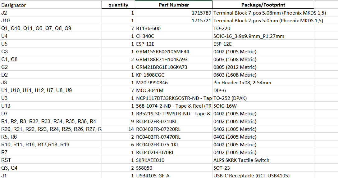
does resistor size affect the flash process? because I used these footprints for my pcb can you please check the BOM file
No, it should not.
The output seems to me like RXD is working (ESP8266 sending to PC) but TXD is not working (PC sending to ESP8266).
Can you actually remove R16 and connect it with a straight solder blob, shorting it directly? The series resistance of 5.1K on TXD may be a bit too much, but still okay on the RXD side..
1 Like
Don’t directly connecting the TX pin will damage anything?
Also thanks for being responsive I appreciate it
No, UART TX from the CH340 at 3.3V levels will go into a UART RX of the ESP8266 which also runs at 3.3V levels, it will not damage anything.
1 Like
I want to thank you so much for giving me proper fix for my problem!!! but i want to ask you one last question what do i do to run into normal mode?
You would have to remove the pulldown of GPIO0 to GND again to make the firmware run as normal. (I guess also its pullup R1 can also be resoldered, just be aware that this will make the U10 optocoupler turn on by default.. again I would have not used GPIO0 to control any other ICs at all.).
If the problem was just that TXD did not go through properly and GPIO15 needed a pulldown, then you can revert all other modifications. The auto-reset circuit formed by Q3 and Q4 should work properly, uploading sketches and resetting the ESP8266 to run them normally.
1 Like
I left GPIO15 pulled down and removed R16 and it started working just fine thank you so much