Hello everyone,
I’m working on my own board which is based on STM32F103C8 which I designed and a very wired something happens with me.
I use st-link v2 to upload my code but after I uploaded my code, it won’t execute!
I tried a simple blink code example, but, without any luck. The voltage over the pin PA4 is always something between half and one volt.
I double checked the voltage over nrst pin (which is pulled down with 100n capacitor to GND) and it’s 3.3V. I checked even BOOT0 and BOOT1 pins (which both pulled down with 10K resistor to GND) and the voltage over them is 0V.
Did I miss something else? Or the IC is just fried and need to change it? Is it possible the IC is broken, but, I can upload any code to it?
Please try and use the unified debugger to see what’s going on. You seem to be already uploading via the stlink so this should work out of the box. If you switch to the “Debug” sidepanel and press the play button, it should start right up.
Does it reach setup()? Is it stuck before that? (Use the pause button to see where). Does it never return from the delay()?
Program
received signal SIGINT, Interrupt.
SystemClock_Config () at C:\Users\tom-4\.platformio\packages\framework-arduinoststm32\variants\Generic_F103Cx\variant.cpp:136

136 while (1);
Please add this code in your main.cpp at the bottom to test if switching to the internal oscillator and not using the external one makes the firmware work.
extern "C" void SystemClock_Config(void)
{
  RCC_OscInitTypeDef RCC_OscInitStruct = {0};
  RCC_ClkInitTypeDef RCC_ClkInitStruct = {0};

  /** Initializes the RCC Oscillators according to the specified parameters
  * in the RCC_OscInitTypeDef structure.
  */
  RCC_OscInitStruct.OscillatorType = RCC_OSCILLATORTYPE_HSI;
  RCC_OscInitStruct.HSIState = RCC_HSI_ON;
  RCC_OscInitStruct.HSICalibrationValue = RCC_HSICALIBRATION_DEFAULT;
  RCC_OscInitStruct.PLL.PLLState = RCC_PLL_ON;
  RCC_OscInitStruct.PLL.PLLSource = RCC_PLLSOURCE_HSI_DIV2;
  RCC_OscInitStruct.PLL.PLLMUL = RCC_PLL_MUL16;
  if (HAL_RCC_OscConfig(&RCC_OscInitStruct) != HAL_OK)
  {
    while(1);
  }
  /** Initializes the CPU, AHB and APB buses clocks
  */
  RCC_ClkInitStruct.ClockType = RCC_CLOCKTYPE_HCLK|RCC_CLOCKTYPE_SYSCLK
                              |RCC_CLOCKTYPE_PCLK1|RCC_CLOCKTYPE_PCLK2;
  RCC_ClkInitStruct.SYSCLKSource = RCC_SYSCLKSOURCE_PLLCLK;
  RCC_ClkInitStruct.AHBCLKDivider = RCC_SYSCLK_DIV1;
  RCC_ClkInitStruct.APB1CLKDivider = RCC_HCLK_DIV2;
  RCC_ClkInitStruct.APB2CLKDivider = RCC_HCLK_DIV1;

  if (HAL_RCC_ClockConfig(&RCC_ClkInitStruct, FLASH_LATENCY_2) != HAL_OK)
  {
    while(1);
  }
}
Well it “works” by not making use of the proper oscillator. The internal one (HSI + PLL) only goes up to 8 * 12 / 2 MHz = 64 MHz instead of the 72MHz full speed with the external oscillator (HSE). Without using HSE, you also can’t use USB, as it needs the more precise crystal.
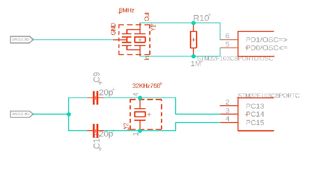
This shows that there is some fault in the oscillator hardware or software configuration. The code it uses is as I’ve linked pretty straight-forward, it assumes an 8MHz crystal (which you have) and uses a PLL multiplier of 9 to get to 72MHz. The error however shows that it cannot start the oscillator or fails to get a lock on the PLL.
There’s nothing really that is .ini configurable in this case that would make sense. The settings of the PLL are constant anyways in the code (mul 9). Changing f_cpu also doesn’t really help (since the F_CPU macro is not used in code anyways in this case), but here are docs anways
There is the HSE_VALUE macro which might get used elsewhere but it also defaults to the correct value already
so doing build_flags = -D HSE_VALUE=somethingelse (docs) won’t make a difference.
So the only thing I can recommend is double checking hardware connections between the oscillator and the MCU. Maybe the attempt at crystal startup is measurable with an oscilliscope? Maybe the oscillator doesn’t work because of too much parasitic PCB capacitance? (I’m not a hardware expert though).
Great work! Thank you again. It’s lot of calculations and I’m tired enough for today. I will try read them tomorrow and check again stm32 design recommendations to find my fault.
I’m sure this would help someone else with the same problem
Sorry for being so late, but, I was so busy.
I discovered the problem which was a wrong soldered resonator! It’s so tiny without any marks for pin 1 or input pin so I turned upside down and it worked without extra coding or clock settings!
I have another question related to STM32F103Cx chip. As I’m new to STM32 world so I used STM32F103C8 chip from blue pill board. I desoldered the chip and soldered again to my board.
My question is, does STM32 brand new chips need bootloader (as ATmega328 chips)?
What settings I need if I wanna use brand new STM32 chip?
Regrds,
Tommy
Flashing via SWD doesn’t even use the bootloader but directly the hardware. All STM32 chips do have a pre-burned bootloader in mask-ROM that you cannot modify or reburn; it’s entered by resetting and having BOOT0 (some have additionally BOOT1) set to a certain voltage and offers that the MCU be additionally flashable via UART, USB, I2C, CAN, …
So you don’t need to worry about a bootloader or settings at all. (If you don’t want anything custom).
See here and here, specifiaclly for the STM32F10xxx devices. They only come with a UART bootloader, although they are USB capabable. That’s why custom USB bootloaders exist.