I have built a custom board with an ES32-S2 chip, I am trying to upload a test sketch to it using the UART and an FTD2204 adapter. It does seem to toggle the IO0 and EN correctly, but it seems it is timing out as folows:
A fatal error occurred: Failed to connect to ESP32-S2: Timed out waiting for packet header
Are ESP32-S2 bare chips missing the bootloader?
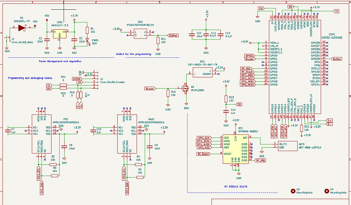
attached also my schematics, can anyone please help? I am frustrated, I have tried everything.
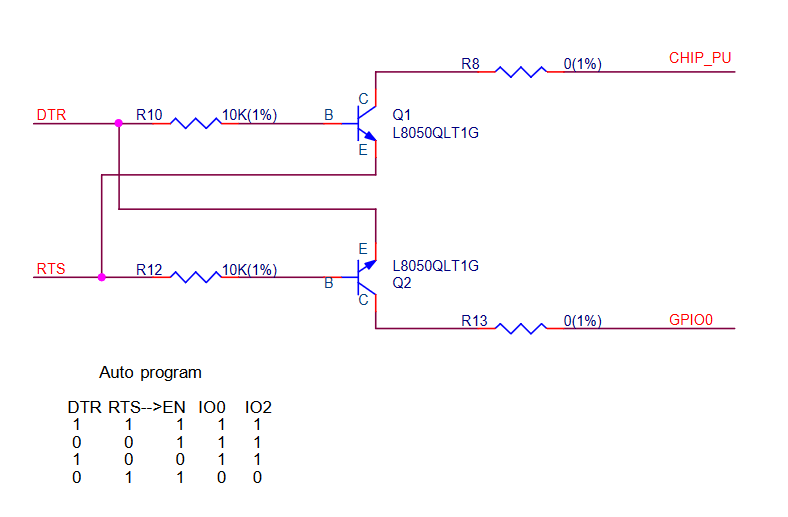
I looked at your schematic but don’t understand it. I am familiar with the regular ESP32 and the auto boot mode uses two a circuit with two transistors between the usb/serial IC and the ESP32 which controls the book/reset sequence. I also don’t have experience with bare ESP32, just modules.
If you think that your circuit is good, I would use a logic analyzer to look at the signals during boot, e.g. a 8 channel Salea or a clone, and compare it to the datasheet.
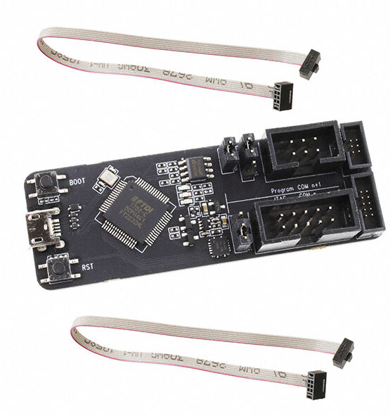
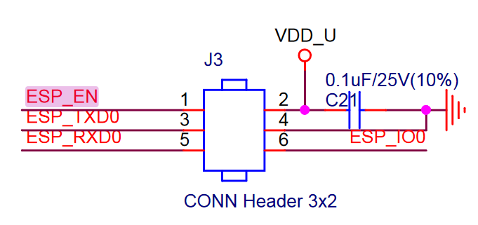
+1 to that. How are you connecting GPIO0 and EN to the ESP-PROG? There is no auto-reset circuit in it. You would have to reset the chip into bootloader mode manually by connecting GPIO0 to GND and then giving the chip power.
Also I assume you have R14 and R15 populated and R16 and R17 unpopulated. You could also try to not use the UART upload mode but the USB upload mode, i.e., populating R16+R17, unpopulating R14+R15, then doing the “enter bootloader mode” proecdure as above (reboot while GPIO0 ↔ GND is connected).
Thank you, however the esp-prog does have the auto reset circuit, and i can see it toggling the pins while tryimg to connect. I have tried every method of manually reset the chip while IO0 is pulled low… No succes…
You were right about the resistors, i am using them as quasi bridges. I anticipated some issue regarding upload using UART…
The is definitely the most mysterious issue i have ever faced… Wierd.
One tging to add, the green led indicator shows that the programmer is chatting on the espRX side. But the blue does not blink at all, seems like the chip is not responding. This is though the third one, cannot be defect.
My bad guys, i didnt know that a xtal was mandatory to run the chip, i didnt have it on my design if you could notice from the schematics. I have to redesign my board… I have the esp32-s2 with the embedded 4mb rom and 2mb ram, is the external flash rom mandatory in this case?