Cannot get Wemos D1 Mini Pro (with CH9102) to upload with esptool.py

This has me completely vexed. I loaded a skeleton project with PlatformIO “New Project” and the platformio.ini file looks like this:

[env:d1_mini_pro]
platform = espressif8266
board = d1_mini_pro
framework = arduino

The barebones project is this:

#include <Arduino.h>
// put function declarations here:
int myFunction(int, int);

void setup() {
// put your setup code here, to run once:
int result = myFunction(2, 3);
}

void loop() {
// put your main code here, to run repeatedly:
}

// put function definitions here:
int myFunction(int x, int y) {
return x + y;
}

When I try to upload, I get this:

Processing d1_mini_pro (platform: espressif8266; board: d1_mini_pro; framework: arduino)
----------------------------------------------------------------------------------------------------------------
Verbose mode can be enabled via `-v, --verbose` option
CONFIGURATION: https://docs.platformio.org/page/boards/espressif8266/d1_mini_pro.html
PLATFORM: Espressif 8266 (3.2.0) > WeMos D1 mini Pro
HARDWARE: ESP8266 80MHz, 80KB RAM, 16MB Flash
PACKAGES:
 - framework-arduinoespressif8266 @ 3.30002.0 (3.0.2)
 - tool-esptool @ 1.413.0 (4.13)
 - tool-esptoolpy @ 1.30000.201119 (3.0.0)
 - tool-mklittlefs @ 1.203.210628 (2.3)
 - tool-mkspiffs @ 1.200.0 (2.0)
 - toolchain-xtensa @ 2.100300.210717 (10.3.0)
LDF: Library Dependency Finder -> https://bit.ly/configure-pio-ldf
LDF Modes: Finder ~ chain, Compatibility ~ soft
Found 35 compatible libraries
Scanning dependencies...
No dependencies
Building in release mode
Retrieving maximum program size .pio\build\d1_mini_pro\firmware.elf
Checking size .pio\build\d1_mini_pro\firmware.elf
Advanced Memory Usage is available via "PlatformIO Home > Project Inspect"
RAM:   [===       ]  34.0% (used 27892 bytes from 81920 bytes)
Flash: [==        ]  24.9% (used 260093 bytes from 1044464 bytes)
Configuring upload protocol...
AVAILABLE: espota, esptool
CURRENT: upload_protocol = esptool
Looking for upload port...
Auto-detected: COM4
Uploading .pio\build\d1_mini_pro\firmware.bin
esptool.py v3.0
Serial port COM4
Connecting........_____....._____....._____....._____....._____....._____....._____

A fatal error occurred: Failed to connect to ESP8266: Timed out waiting for packet header
*** [upload] Error 2
============== [FAILED] Took 26.46 seconds ====================

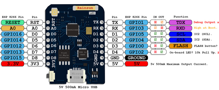
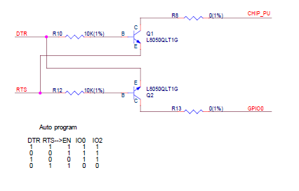
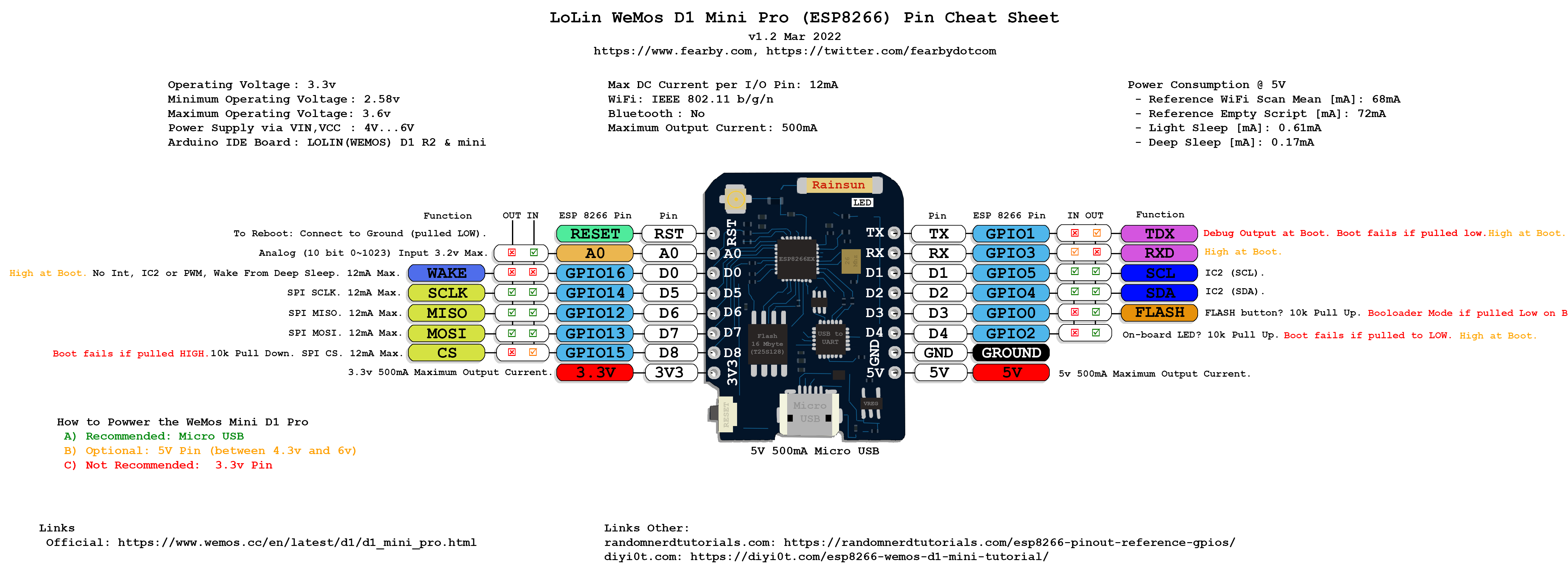
I’ve tried grounding D0 and holding reset switch while uploading to no avail. I disabled the driver and re-enabled it. The on-board LED flashes so it seems to try to load but maybe the board is defective? I want to use the D1 Mini Pro because of the UFL external antenna connector since I need more range for my weather station project. Any help would really be appreciated while I still have hair left.

Why “D0”? The bootloader pin on an ESP8266 is GPIO0. The “Dx” pin numbering is completely arbitrary on the board and does not correspond to the ESP8266’s GPIO pin numbering system at all.

From https://fearby.com/wp-content/uploads/2022/03/WeMosMiniD1ProGuide.png

So according to that, you would have to connect D3 to GND and power cycle the board to get it to enter bootloader mode.

Another thing to try though would be to try ever availble reset method one by one. After all, auto-reset-into-bootloader should work if the USB-UART adapter is properly connected with a auto reset circuit to the ESP8266.

https://docs.platformio.org/en/latest/platforms/espressif8266.html#reset-method

Thanks Max! It uploads now. Yeah, momentary brainfart, I think. Not sure why I thought D0 was the bootloader pin to ground. But now with this WCH CH9102 USB-Serial chip, after the good upload, when I go to the platformIO serial monitor, I get garbage from the serial port - both at 9600 baud and 115200 (which device manager says the port is set at). I’m fairly new at Espressif devices, but I don’t understand this CH9102 chip. I have another D1 Pro with a SIL CP2104 chip and that works fine. The whole reason I want to use this D1 Pro is for extended range. Here’s the simple webserver code I grabbed to test the range of the device. Thanks again for your help!

/*
 * ESP8266 NodeMCU AJAX Demo
 * Updates and Gets data from webpage without page refresh
 * https://circuits4you.com
 */

#include <ESP8266WiFi.h>
#include <WiFiClient.h>
#include <ESP8266WebServer.h>

#include "index.h"  //Our HTML webpage contents with javascripts
#include "Finn.h"   // IP info here.
#define LED D6  //On board LED

void handleRoot();
void handleLED();
void handleRSSI();

ESP8266WebServer server(80); //Server on port 80

//===============================================================
// This routine is executed when you open its IP in browser
//===============================================================
void handleRoot() {
 String s = MAIN_page; //Read HTML contents
 server.send(200, "text/html", s); //Send web page
}

void handleRSSI() {
  long rssi = WiFi.RSSI();
  Serial.print("Signal strength (RSSI): ");
  Serial.print(rssi);
  Serial.println(" dBm");
  //int a = analogRead(A0);
  String rssiValue = String(rssi);
  server.send(200, "text/plane", rssiValue); //Send ADC value only to client ajax request
}

void handleLED() {
 String ledState = "OFF";
 String t_state = server.arg("LEDstate"); //Refer  xhttp.open("GET", "setLED?LEDstate="+led, true);
 Serial.println(t_state);
 if(t_state == "1")
 {
  digitalWrite(LED, HIGH);    //LED ON
  ledState = "ON";            //Feedback parameter
 }
 else
 {
  digitalWrite(LED, LOW);     //LED OFF
  ledState = "OFF";           //Feedback parameter  
 }
 
 server.send(200, "text/plane", ledState); //Send web page
}

//==============================================================
//                  SETUP
//==============================================================
void setup(void){
  Serial.begin(9600);
  
  WiFi.begin(WLAN_SSID, WLAN_PASSWD);     //Connect to your WiFi router
  Serial.println("");

  //Onboard LED port Direction output
  pinMode(LED,OUTPUT); 
  
  Serial.print("Connecting to ");
  Serial.println(WLAN_SSID);

  // Wait for connection
  while (WiFi.status() != WL_CONNECTED) {
    delay(500);
    Serial.print(".");
  }

  //If connection successful show IP address in serial monitor
  Serial.println("");
  Serial.print("IP address: ");
  Serial.println(WiFi.localIP());  //IP address assigned to your ESP
 
  server.on("/", handleRoot);      //Which routine to handle at root location. This is display page
  server.on("/setLED", handleLED);
  server.on("/readRSSI", handleRSSI);

  server.begin();                  //Start server
  Serial.println("HTTP server started");
}
//=========================================================
//                     LOOP
//=========================================================
void loop(void){
  server.handleClient();          //Handle client requests
}

If you’re using PlatformIO’s builtin serial monitor, you have to set the monitor speed in your platformio.ini:

[env:d1_mini_pro]
platform = espressif8266
board = d1_mini_pro
framework = arduino
monitor_speed = 9600

See also monitor_speed — PlatformIO latest documentation

Thanks for the tip, but same thing. It seems to load fine but even with specifying the monitor speed and same in the sketch, I get garbage on output. Below are my platform.ini file and the output from uploading. Not having much luck with this CH9102 chip…it’s supposedly better than the CP2104, but the latter works. Also, grounding GPIO0 DOES work, but I’m wondering why this is the only board that needs that. :frowning:

[env:d1_mini_pro]
platform = espressif8266
board = d1_mini_pro
framework = arduino
monitor_speed = 9600

Executing task in folder Web-Server-LED-Control-AJAX: C:\Users\bruce.platformio\penv\Scripts\platformio.exe device monitor

— Terminal on COM4 | 9600 8-N-1
— Available filters and text transformations: colorize, debug, default, direct, esp8266_exception_decoder, hexlify, log2file, nocontrol, printable, send_on_enter, time
— More details at Redirecting...
— Quit: Ctrl+C | Menu: Ctrl+T | Help: Ctrl+T followed by Ctrl+H
�Htx6

Please set monitor_speed = 76800 in your platformio.ini and post the result here.

Thanks, Boris, for the reply. Well, this is very interesting. Here is the result:

Executing task in folder Web-Server-LED-Control-AJAX: C:\Users\bruce.platformio\penv\Scripts\platformio.exe device monitor
— Terminal on COM4 | 76800 8-N-1
— Available filters and text transformations: colorize, debug, default, direct, esp8266_exception_decoder, hexlify, log2file, nocontrol, printable, send_on_enter, time
— More details at Redirecting...
— Quit: Ctrl+C | Menu: Ctrl+T | Help: Ctrl+T followed by Ctrl+H
ets Jan 8 2013,rst cause:2, boot mode:(1,7)

If I press reset, it outputs same thing.

Boot mode 1,7 means it is still in upload mode and the ESP is waiting for uploading a new sketch! See Boot Mode Selection - ESP8266 - — esptool.py latest documentation

Check the strapping pins - See Boot Mode Selection - ESP8266 - — esptool.py latest documentation

Maybe your board needs special settings for monior_rts and -dtr. Please try all combinations of monitor_rts and monitor_dtr one by one in your platformio.ini:

monitor_rts = 0
monitor_dtr = 0
monitor_rts = 1
monitor_dtr = 0
monitor_rts = 0
monitor_dtr = 1
monitor_rts = 1
monitor_dtr = 1

OK, thanks again Boris for working with me. Here is the first one with rts = 0 and dtr = 0

— forcing DTR inactive
— forcing RTS inactive
— Terminal on COM4 | 76800 8-N-1
— Available filters and text transformations: colorize, debug, default, direct, esp8266_exception_decoder, hexlify, log2file, nocontrol, printable, send_on_enter, time
— More details at Redirecting...
— Quit: Ctrl+C | Menu: Ctrl+T | Help: Ctrl+T followed by Ctrl+H

ets Jan 8 2013,rst cause:2, boot mode:(3,6)

load 0x4010f000, len 3460, room 16
tail 4
chksum 0xcc
load 0x3fff20b8, len 40, room 4
tail 4
chksum 0xc9
csum 0xc9
v0004a7c0
~ld
��␀␀�␀�␀����␀��␀����␀��␀�␀���␀��␀���␀�␀␀␀�����␀␀(more garbage)

Here is the next one with rts = 1 and dtr =0
(Interesting… NOTHING on output, even after pressing reset button)
— forcing DTR inactive
— forcing RTS active
— Terminal on COM4 | 76800 8-N-1
— Available filters and text transformations: colorize, debug, default, direct, esp8266_exception_decoder, hexlify, log2file, nocontrol, printable, send_on_enter, time
— More details at Redirecting...
— Quit: Ctrl+C | Menu: Ctrl+T | Help: Ctrl+T followed by Ctrl+H

Next one with rtc=0 and dtr =1

— forcing DTR active
— forcing RTS inactive
— Terminal on COM4 | 76800 8-N-1
— Available filters and text transformations: colorize, debug, default, direct, esp8266_exception_decoder, hexlify, log2file, nocontrol, printable, send_on_enter, time
— More details at Redirecting...
— Quit: Ctrl+C | Menu: Ctrl+T | Help: Ctrl+T followed by Ctrl+H

ets Jan 8 2013,rst cause:2, boot mode:(3,6)

load 0x4010f000, len 3460, room 16
tail 4
chksum 0xcc
load 0x3fff20b8, len 40, room 4
tail 4
chksum 0xc9
csum 0xc9
v0004a7c0
~ld
��␀␀�␀�␀����␀��␀����␀��␀�␀���␀��␀���␀�␀␀␀�����␀␀�␀���␀��␀�␀␀���␀�������␀����␀␀�␀␀�␀␀�␀␀�␀␀�␀␀�␀␀�␀␀�␀␀�␀␀�␀␀�␀␀�␀␀�␀␀�␀��␀␀�␀�␀␀�␀��␀␀�␀�␀␀�␀␀�␀␀���␀��␀��␀�␀�␀␀␀�␀␀␀␀␀�␀␀␀␀�␀␀␀␀�␀(lots of garbage)

Last one, with rts=1 and dtr=1

— forcing DTR active
— forcing RTS active
— Terminal on COM4 | 76800 8-N-1
— Available filters and text transformations: colorize, debug, default, direct, esp8266_exception_decoder, hexlify, log2file, nocontrol, printable, send_on_enter, time
— More details at Redirecting...
— Quit: Ctrl+C | Menu: Ctrl+T | Help: Ctrl+T followed by Ctrl+H
␀�␀␀�␀␀�␀␀�␀␀�␀␀�␀␀�␀␀�␀␀�␀␀�␀␀�␀��␀␀�␀�␀␀�␀��␀␀�␀�␀␀�␀␀�␀␀���␀��␀��␀�␀�␀␀␀�␀␀␀␀␀�␀␀␀␀�␀␀␀␀�␀�␀␀␀␀␀␀␀��␀␀�␀␀␀�␀���␀���␀��␀␀�␀���␀�␀␀�␀����␀�␀␀�␀␀�␀�␀���␀�␀␀�␀����␀�␀␀���␀␀�␀
ets Jan 8 2013,rst cause:2, boot mode:(1,6) (pressed reset button here).

The first 3 look good. Bootmode 3,x means the sketch is running.

The garbage is due to the fact that your sketch works with a baud rate of 9600, but the monitor is currently set to 76800.

Stay with the first one (monitor_dtr = 0 / monitor_rts = 0) and change the baud rate back to 9600:

[env:d1_mini_pro]
platform = espressif8266
board = d1_mini_pro
framework = arduino
monitor_speed = 9600
monitor_rts = 0
monitor_dtr = 0

Now you should see the output form your sketch.

Super!! Thanks so much for the assist, Boris! I am perplexed though why I had to bring GPIO0 to ground in order to upload. Except for a bare-bones ESP01 I was experimenting with, I never before had to do that. Also, setting RTS and DTR in the platformio.ini is something I didn’t have to do with other boards. I’m wondering if this is specific to the CH9102 USB-serial converter or just the board I go from Aliexpress. Pretty weird to have to do these things because of a different chip, in my opinion. I’ll leave this open for a bit for comments. But I got it working thanks, Boris and Max!!

I would say it’s just about your the board you’re using.

I never encountered such issues on my boards (DevKit-C clones)

Yeah, I’m figuring that it’s the board. Thanks to you (and Max) I know what to do if this comes up again. Just out of curiosity, where did you get the idea to set RTS and DTR to 0 - did you see that in the CH9102 chip specs PDF?

It is about how the auto-reset circuit is implemented on your board.

Here is the original reference design by Espressif:

image

But this is where my knowledge ends. :innocent: