I am building a project for a custom board using the MCU stated in title. I am setting it up with an arduino frame work, on setting up the project I have selected a nucleoboard using an MCU in the STM32G4 family.
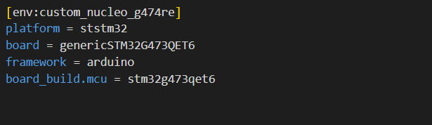
My platfomio.ini file looks as follows:
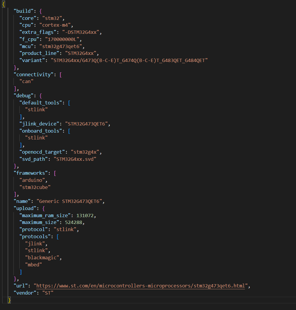
My .json file for the custom board looks as follows:
I have duplicated a variants folder for my mcu from C:\Users\<users>\.platformio\packages\framework-arduinoststm32\variants. I replaced the linker script in the duplicated folder with one i produced from stm32cubemx for my MCU.
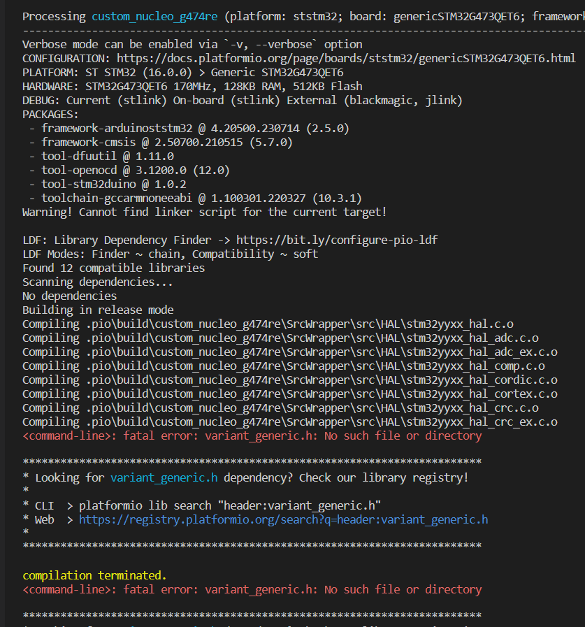
After doing all of this I am still unable to get a build and get these error messages :
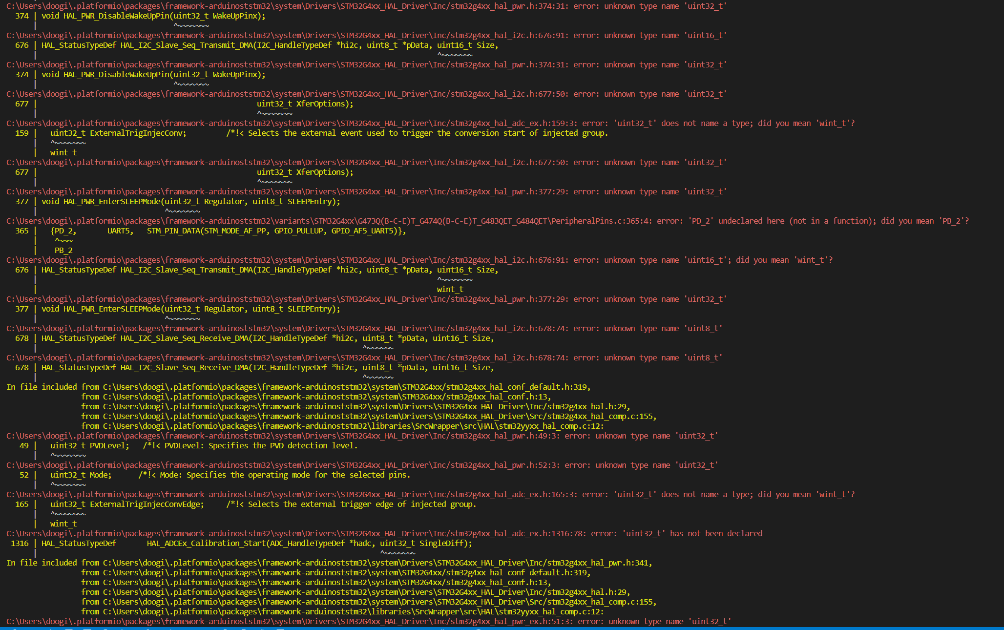
I then attempted a build, the terminal started spitting out error after error and appeared to continue forever, so I terminated the build and took a screenshot of the errors. It appears it’s not accepting the stdint.h types :
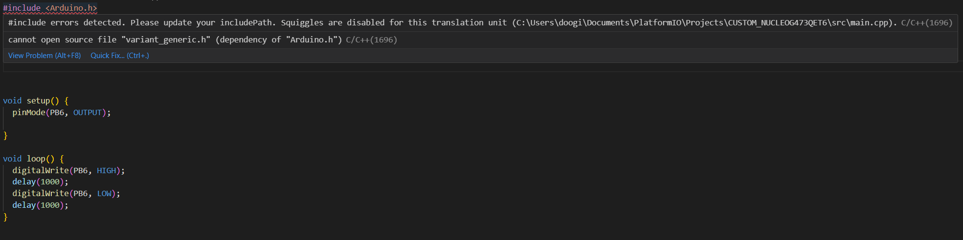
That did the trick. The project builds and I can upload now, however I am now getting an error for the include <Arduino.h> and nothing happens when I upload a simple blinky program onto my board. I’m assuming that is because of the include error.
If the project builds, it must have found Arduino.h and it’s just the VSCode intellisense lagging behind.
Trigger a rebuild of the intellisense in the easiest possible way: Ctrl+Shift+P → Reload Window (or “Rebuild Intellisense Index”).
The code looks good for PB6. It should also hit the clock init code for HSI + PLL (so no external quartz crystal is assumed) here.
After the window has reloaded per above, and given you’re uploading via ST-Link, you should be able to debug the project. Set a breakpoint in your setup() and loop() function then use the debugging sidebar → Play button on “PIO Debug”. Does it hit the breakpoint in setup? If not, press the “pause” button and see where it is stuck in the backtrace.
Okay I have reloaded VSCode and rebuilt and uploaded the project, added the breakpoints in and started the debugger. Like I said before, this is all new to me so I’m struggling to interpret whats going on.
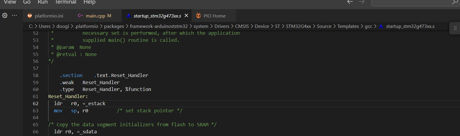
The start up file is opened once the program stars debugging at line 62 as follows:
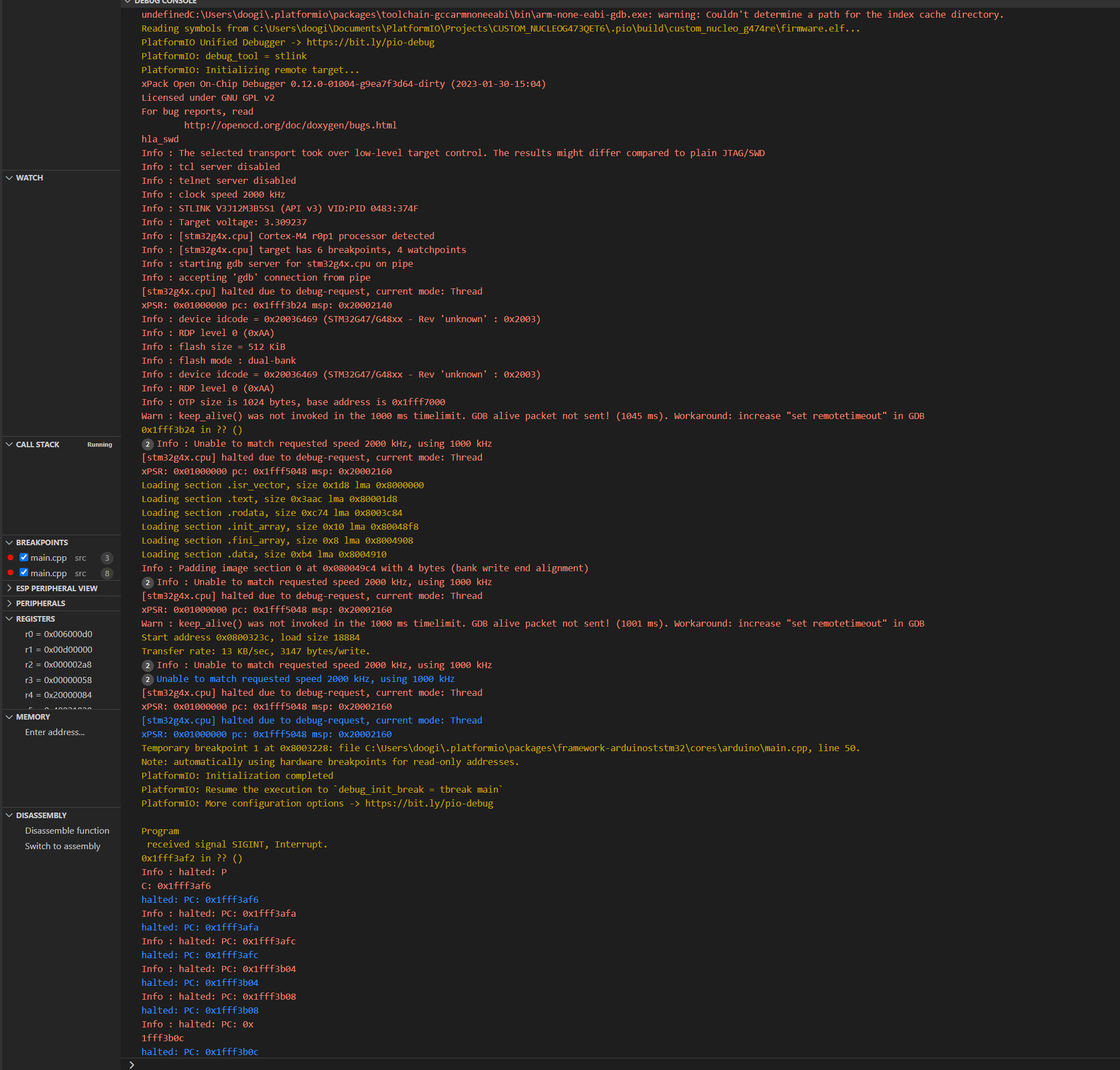
I’m not too sure where to go from here so I will share with you the debuggere console, nothing is happening on my board in regards to the blinky program.
Apologies if I haven’t done what you have asked, I’m a bit unsure if it’s hitting the breakpoint or not but I don’t think it is, how do i check where it is on the backtrace?
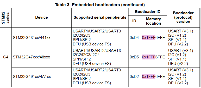
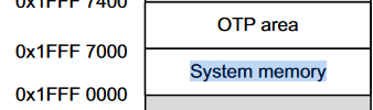
The microcontroller uses the state of the BOOT0 and BOOT1 pins to decide when to jump to this bootloader code. Per the linked PDF, both these pins should be connected to GND (e.g. directly or via a pulldown resistor) if you want the chip to execute the uploaded firmware (0x8000000) instead of the bootloader code.
What does that look like on your custom board? Hopefully you didn’t leave these pins unconnected or hard-connected to +3.3V?