Hello, everyone!
Has anyone found a good way (or designed/made a board) to make it easier to debug the arduino nano 33 BLE sense board? I’m trying to avoid simply soldering wires to the board as, over time, a wire could come lose, short something out and damage either the board or the debugger itself.
It looks like it has 5 pads for debugging but, for whatever reason, they didn’t end up placing pads for a header. I’m debating trying to solder a SMT header to those pins but thought I’d check in here to see if anyone else designed a board for this purpose.
It looks like @manuelbl desgned a board in another thread (Like if you have an nRF52840: Nordic USB dongle, Arduino Nano 33 BLE, Adafruit, Sparkfun, April, Makerdairy, Fanstel, Particle or any other - #5 by rocksetta) but it doesn’t look like the design files were posted there.
Anyway, I was hoping to find the best way to debug the board without soldering wires to it and thought someone in here might have an idea. Any recommendations would be greatly appreciated! Thanks, everyone!
PCB in EsayEDA: https://easyeda.com/manuelbl/arduino-nano-debug-adapter
STL file for Arduino Nano 33 BLE: https://www.filebin.ca/5CykRVi6ar0j/Nano33SWDBracket.stl
STL file for Arudino Nano IoT: https://filebin.ca/5Cyl8Hgs0CIL/NanoIoTSWDBracket.stl
The Arduino Nano 33 BLE and IoT boards differ by about 1mm (in length). So they require two slightly different brackets
The 3D print needs to be quite precise. Otherwise the Arudino Nano has too much play and the pogo pins do not reliablily align with the contacts. I recommend to print it using a layer height of 0.1mm and use PLA or a material with a similar rigidity (Nylon is too flexible).
The pogo pins are from AliExpress: https://www.aliexpress.com/item/32883962541.html
If you use the raiser board (for the version with the pin headers with long pins), you will likely need create/print a jig so you can solder the raiser board at the exact height and without an angle.
That’s perfect! Any chance you have the BOM (it looks empty on the easyEDA page). If not, no big deal, most of them look like pretty standard parts on Digikey, I can probably find them (though knowing the header heights in particular would be pretty helpful. Definitely looks like J7 is shorter than the average header and J1 and J2 definitely sit higher). Thought I’d ask all the same. Thanks!
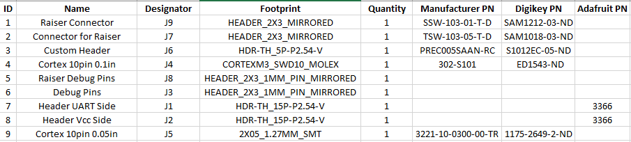
This is my best guess:
Below is a text version of the above for ease of copying and pasting (it’s just formatted terribly to the point where it’s unreadable. Hopefully the above makes it a bit more readable).
ID Name Designator Footprint Quantity Manufacturer PN Digikey PN Adafruit PN
1 Raiser Connector J9 HEADER_2X3_MIRRORED 1 SSW-103-01-T-D SAM1212-03-ND
2 Connector for Raiser J7 HEADER_2X3_MIRRORED 1 TSW-103-05-T-D SAM1018-03-ND
3 Custom Header J6 HDR-TH_5P-P2.54-V 1 PREC005SAAN-RC S1012EC-05-ND
4 Cortex 10pin 0.1in J4 CORTEXM3_SWD10_MOLEX 1 302-S101 ED1543-ND
5 Raiser Debug Pins J8 HEADER_2X3_1MM_PIN_MIRRORED 1
6 Debug Pins J3 HEADER_2X3_1MM_PIN_MIRRORED 1
7 Header UART Side J1 HDR-TH_15P-P2.54-V 1 3366
8 Header Vcc Side J2 HDR-TH_15P-P2.54-V 1 3366
9 Cortex 10pin 0.05in J5 2X05_1.27MM_SMT 1 3221-10-0300-00-TR 1175-2649-2-ND
Overall, I think I’m close but the parts that looked like they might cause the biggest issues are:
J1 and J2 (insulation and mating pin length)
J7 and J8 (mating pin length)
Thanks for your help!
Most of the parts that I have used have already been in my parts bin. So I don’t have any detail specs. Here are some hints though:
All connectors use a 2.54mm / 0.1in grid except for the small Cortex connector (J3/J8) using a 1.27mm/0.05in grid. Only one of them is fitted depending on whether a raiser board is used or not. When fully extended, the pogo pins extend to about 7mm above the PCB they are soldered on. If yours are different, you need to adapt the 3D printed bracket accordingly or - if you use the other setup with the raiser board - adjust the height of the raiser board.
For J7: I didn’t have header pins with exactly the needed height. It might not even exist. So I had to solder the raiser board such that it sits somewhat higher than flat on the headers. In order to do so, I created a jig holding the raiser board at the correct height and sufficiently level during soldering.
J1 and J2 are only needed if the raiser board is used. If they don’t have the exact same height as mine, you can adjust the raiser board height accordingly (see above). In my case, they are 8.4mm high and have pins that protrude about 10mm.