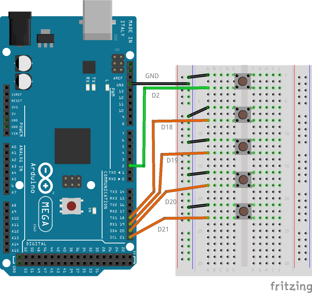
I dug out my Mega2560 board and had a play. Here’s the breadboard layout I used.
The attached sketch will hopefully help you see what’s going on.
/*
 MEGA2560, sleep  modes and INTx wake up calls.

There are 5 switches attached to pins D2, D18, D19, D20 and D21.
The switches connect to GND when pressed. The pins are all INPUT_PULLUP.

Pressing a switch attached to D2 will NOT wake up from anything other
than SLEEP_MODE_IDLE, but as Timer 0's overflow is in use to update
millis() and micros(), the board will be awake anyway.

Pressing any of the other swicthes will cause the board to wake. It
will tell you which swoicth was pressed, before going back to sleep.


Norman Dunbar
For community.platformio.org.
17 October 2022.
*/

#include <avr/sleep.h>

volatile byte whichPin = 0;

void int2ISR() {
    // Triggers when pin D21 changes.
    whichPin = 21;
}


void int3ISR() {
    // Triggers when pin D20 changes.
    whichPin = 20;
}


void int4ISR() {
    // Triggers when pin D19 changes.
    whichPin = 19;
}


void int5ISR() {
    // Triggers when pin D18 changes.
    whichPin = 18;
}


void int0ISR() {
    // Triggers when pin D2 changes.
    whichPin = 2;
}


void setup() {
    Serial.begin(9600);

    // Pins 2, 18-21 are INPUT_PULLUPs.
    pinMode(2, INPUT_PULLUP);
    for (byte p = 18; p < 22; p++) {
        pinMode(p, INPUT_PULLUP);
    }

    // Attach interrupts to all 5 pins.
    attachInterrupt(digitalPinToInterrupt(2),  int0ISR, FALLING);
    attachInterrupt(digitalPinToInterrupt(18), int5ISR, FALLING);
    attachInterrupt(digitalPinToInterrupt(19), int4ISR, FALLING);
    attachInterrupt(digitalPinToInterrupt(20), int3ISR, FALLING);
    attachInterrupt(digitalPinToInterrupt(21), int2ISR, FALLING);

    // Which sleep mode shall I use? If you change this to
    // SLEEP_MODE_IDLE you won't need to press a button.
    set_sleep_mode(SLEEP_MODE_PWR_DOWN);
}


void loop() {
    Serial.println("I'm going to sleep now.");
    delay(250);

    // The manual says to do it this way!
    noInterrupts();
    sleep_enable();
    interrupts();

    // Go to sleep with interrupts running.
    sleep_cpu();

    // I'm awake, disable sleep.
    sleep_disable();

    // Tell the world we are awake.
    Serial.print("I'm awake, thanks to pin D");
    Serial.println(whichPin, DEC);

    // And then go back to sleep on the next iteration of loop().
    delay(250);
}
When running, it will display a message, then go into sleep mode. If you press one of the switches, it will wake up and tell you which switch got pressed, then go back to sleep. The D2 switch will not wake the MCU and will not display a message.
I'm going to sleep now.
I'm awake, thanks to pin D18
I'm going to sleep now.
I'm awake, thanks to pin D19
I'm going to sleep now.
I'm awake, thanks to pin D20
I'm going to sleep now.
I'm awake, thanks to pin D21
I'm going to sleep now.
It doesn’t matter how long you hold the button down for, the message will appear once, because the ISR function was triggered by the pin state falling to GND and not because it is being held there.
If you run the code as above, the MCU will go into Power Down sleep mode. Press the D2 switch and nothing happens. This would be the case if there was another switch on D3 as well, neither of those two switches will wake the board unless they are configured with a low interrupt trigger. LOW.
If you press any other switch, you get a message telling you that the board is awake and the name of the pin that woke it.
Change 1
Now, in setup(), change SLEEP_MODE_PWR_DOWN to SLEEP_MODE_IDLE and don’t press any buttons. You will see this in the Serial Monitor:
I'm going to sleep now.
I'm awake, thanks to pin D0
I'm going to sleep now.
I'm awake, thanks to pin D0
...
This is because of the Timer 0 overflow interrupt. It mentions D0 but that’s because whichPin is initialised to zero.
Change 2
Change setup() back to SLEEP_MODE_PWR_DOWN.
Change attachInterrupt(digitalPinToInterrupt(2), int0ISR, FALLING) to attachInterrupt(digitalPinToInterrupt(2), int0ISR, LOW).
Now when you quickly press the switch attached to D2, you’ll get multiple messages like:
I'm going to sleep now.
I'm awake, thanks to pin D2
I'm going to sleep now.
I'm awake, thanks to pin D2
I'm going to sleep now.
...
This is because a LOW level interrupt keeps on triggering for as long as the LOW level is present on the pin. You might be able to press and release quickly due to the delays I have in the code – those were put there to ensure that the messages could be read in the Serial Monitor. Without the delays, the MCU went back to sleep and the message text was not seen when it should have been.
Change 3
Feel free to change the triggering modes on the D18 to D21 switches to RISING, FALLING or CHANGE as desired, and try the code again.
- If you use
RISING nothing will happen until you release the switch.
- If you use
FALLING the message will appears when the switch is pressed.
- If you use
CHANGE you will see a message when the switch is pressed and another when it is released.
- And, as you have seen, using
LOW means you get a messages for as long as you hold down the switch.
In none of the above cases, does pressing one button cause other interrupt functions to trigger, so I am assuming (never assume!) that you either have a configuration problem, a floating input pin or the pins are actually being triggered correctly. Oh yes, if your pins are OUTPUT and the code changes state with digitalWrite(), the interrupt will trigger if you write the trigger condition to the pin.
Hopefully, this has been helpful in helping you understand what is happening with your configuration.
Cheers,
Norm.