I am trying to make my adafruit RP2040 which I program with the arduino framework to recognize it has a usb connected to it. Once it recognizes a usb then turn the tft display backlight off.
What I have so far works but I have to restart or reopen the serial monitor for it to work. Is there an other way to have the program know a usb is connected without having to restart the serial monitor?
bool usbConnected = false;
bool screenTurnedOff = false;

void setup(void)
{
  pinMode(10, OUTPUT); // display backlight pin
  Serial.begin(115200);
  delay(50);
}
void loop(void)
{
  while (Serial)
  {
    digitalWrite(10, LOW); // turn off backlight of screen
    usbConnected = true;
    screenTurnedOff = true;
    Serial << "USB connected" << endl;
    delay(2000);
  }
  if (usbConnected == true)
  {
    usbConnected = false;
    while (screenTurnedOff == true)
    {
      screenTurnedOff = false;
      digitalWrite(10, HIGH); // turn on backlight of screen
      Serial << "Turn screen back on." << endl;
    }
  }
What core / platformio.ini are you working with? The ArduinoCore-mbed and Arduino-Pico core are different.
If you are using TinyUSB under the hood, there are more direct API functions that check if the computer (the USB host) has enumerated the device; So this will return true once the device is plugged into the computer, no serial monitor has to have been opened for that.
In Arduino-Pico, the if(Serial) check goes to the boolean operator, which goes to tud_cdc_connected()
which is in turn the logical AND of the general “is USB connected / ready” and “was the serial monitor connected”, as indicated by the virtual “DTR” line.
I need to read up more on that… But that means that the “unplugged” event is never triggered which would cause it to go register as not connected again.
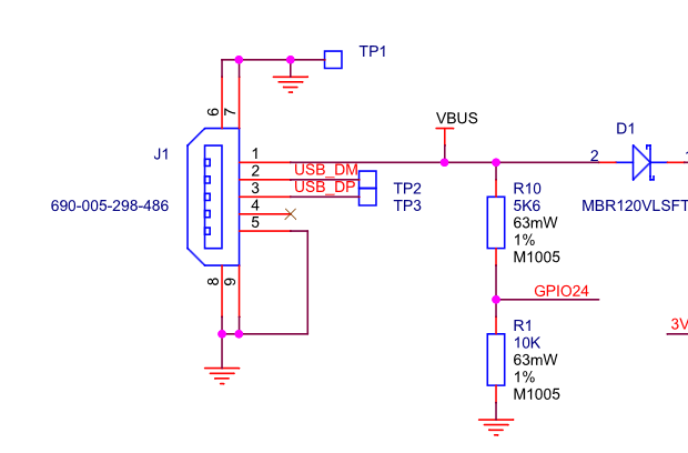
That means you can Create the same 5.6K / 10K votlage divider as formed above by R10 and R1, and connect the middle to a free GPIO pin. Then yoa can just digitalRead() on that pin. If you have two resistors of the same ratio, you can recreate the circuit.
The voltage divider is just there to downconvert 5V into about 3.3V, or, 5V * 10K * (10K + 5.6K) = 3.2V, since the GPIOs can’t handle 5V.
Interesting. Well that sucks. Thanks for looking into this on the platformIO side with me.
That is a lot more information compared to what I was able to find myself. The voltage divider is a good idea that you bought up for the adafruit feather.
Essentially I am testing the Adafruit Feather rp2040 first because I have designed a board where I was trying to do this with the display and usb. I have already made the board and have it on hand.
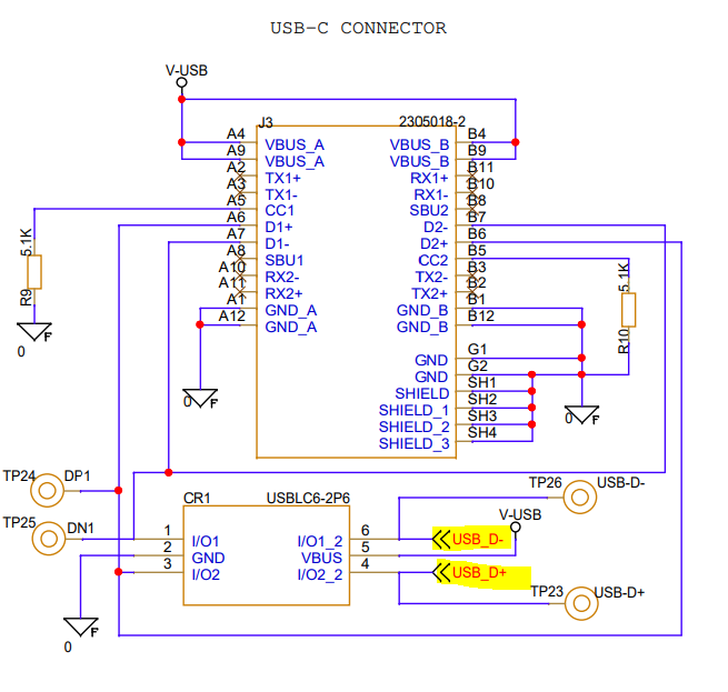
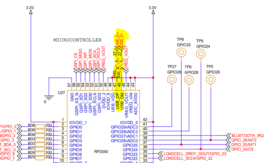
Although I do have this ESD chip right after the USB connector. And from that ESD chip it has D+ and D- and their associated test points which I measured were 3.3 volts when the USBC is connected to a power outlet. D+ and D- actually goes straight into the RP2040 pins 47 and 46. So I took D+ and D- to an open GPIO and read them as inputs. Unfortunately, the digital reading of D+ and D- didn’t always come up as consistent until some minutes later. So it was an unstable way to detect usb connection.