Hope you are doing well as you read these messages. I am trying to interface this MAX31855 Thermocouple Board with an Arduino DUE but it seems as if this made more so for the Uno and Mega. Don’t have much yet but just hoping someone out there has some experience with this device. Regardless, I appreciate the time and patience.
Because of 5V logic level conversion happening on that board? The chip just uses a 3-wire SPI connection, so it’s not inherently incompatible with the Due or someting.
I am using the SEN-30004: MAX31855 4-Ch Thermocouple Arduino Uno Shield.
I was told by customer service that the SPI is broken into the D10-D13 pins, so I was thinking I could maybe rewire those pins to the ICSP pins under the shield and on the Arduino.
The only problem in the schematic I’m seeing is that they’re converting the 3.3V signals of the MAX chip into 5V. The Due is a 3.3V device and would not like 5V levels. The location of the SPI pins should be the same on the Arduino connector though so hardware SPI would still work.
Sadly the board doesn’t have nicely configurable jumpers to disable / bypass the 5V translator. So I can only recommend to buy the Adafruit breakout and try it with the Adafruit’s library.
I hope you know that you have arguably taught me more than most of my hardware professors! I will look into this and get back to you. It seems like having the DUE makes a lot of things a bit more complicated!
Also, some of the files that are included in the libraries given to me by customer service are calling AVR files, which I believe to be UNO or MEGA files. Meaning that I’d need to find new libraries that support the DUE? Is this assumption correct?
AVR would indeed be microprocessor type found in the Uno or Mega boards. The Due has a Atmel SAM / ARM type core after all. So if the given reference library is hardcoded to use AVR-microcontroller specific registers, it won’t compile for a Due. But assuming you’re not running baremetal but use the Arduino framework instead, the above linked Adafruit library will work perfectly fine for all boards, since it only relies on the standardize SPI library interface present in every Arduino core.
So the SPI is broken out to pins D10-D13, so I was told by customer service that I needed to rewire pins D12 and D13 to the SPI pins out on top of the Arduino.
However, when trying to give the Adafruit_MAX31855 library, I received an error after working with the code for a little bit. The error is simply that I am getting a print statement saying that there is no thermocouple connected.
I sniffed the ports and it seems as if I am reading the correct signals. Meaning that I can see the chip select pin getting set to 0 when data should be sent. And I also was able to see that the clock and MISO pins were sending what they are supposed to. I am assuming that the Adafruit libraries were perhaps specifically made for the UNO/MEGA
I also tried the manufactures’ code but like I said I am getting an error with ‘util/delay.h’. When searching this on google, it seems to be AVR specific code, therefore I will forget this part and focus on the Adafruit libraries.
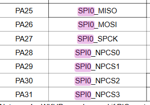
When I read the Due chip’s datasheet the SPI0 pins are on
which per pinout are actually only in the middle ICSP-style connector ("A.25, “A.26”, “A27”). Are you using those pins for the SPI connection?
But again, the more pressing problem is the level conversion. You’d at least want to downshift the MISO data (i.e. the data coming from the sensor into the Due) from 5V to 3.V using a level shifter, e.g. implemented as a simple resistor divider, see How to Level Shift 5V to 3.3V | Random Nerd Tutorials
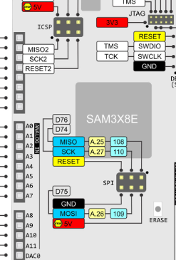
I am using the SPI pins on the DUE. A.25 and A.27. As shown in the following image, to my understanding, the SPI pins are where I am supposed to be connected to:
I am willing to try the other connections since you are using the datasheet. Can you tell me if I made a mistake?
That plus common GND between the shield and your board plus 5V and 3.3V supply plus the resistive divider on MISO (A.25) and the hardware connections should be fine.
So I think I am still confused on what you mean when saying I must add a resistive circuit to the MISO pin. For some reason now I am getting temps from the setup. They are off by <10 degrees but it seems to be functioning. But besides the resistive divider, I think I have the rest. I am having trouble grasping the issue with not having the resistive divider on the MISO due to the functionality of the shield working. Genuinely curious as to how this effects this project.
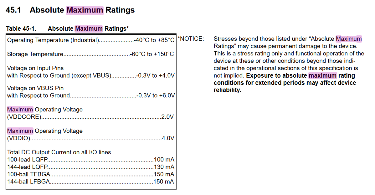
Feeding more than 4.0V in a Due’s I/O pin (such as the 5V MISO coming out from the voltage level translator) is beyond the maximum operating range and thus the manufacturer claims damage can ensue.
I am able to measure 4 different temperatures correctly. Now I am taking what you told me into consideration and am going to test the voltages before running the module for prolonged periods of time. I am having trouble on figuring out what to probe with, given such a tiny amount of space to work with.
So I probed the 2 SPI pins I am using and I only received ~3.2V from the MISO pin and even less from the SCK pin. I do not detect a 5V pin, unless I am doing something wrong. Would you like to see my setup? Or is it all okay considering I tested voltages while running and found none above 4V.
But you are supplying the thermocouple board with 5V? Not that you’re running in the case where you’re only giving it 3.3V as input voltage and then the LDO drops a bit but still powers the chips