Hello Everyone.
So to be able to use arduino function like digitalRead() and others, I modified theses files :Variant.cpp → I added
...extern "C" const PinMuxCfg_t g_pin_cfg[] = {
...
  { BSP_IO_PORT_02_PIN_15,    P215   }, /* (27) DI100 */
  { BSP_IO_PORT_02_PIN_14,    P214   }, /* (28) DI101 */
}
pins_arduino.h → I added
static const uint8_t D100 = 27u;
static const uint8_t D101 = 28u;
And pinmux.inc → I added to avoid compilation error
const uint16_t P214[] = {
PIN_PWM|CHANNEL_0|LAST_ITEM_GUARD
};

const uint16_t P215[] = {
PIN_ANALOG|CHANNEL_0|LAST_ITEM_GUARD
};
My sketch compile and upload to the pcb without error, but when I try to read something on D100 or D101, nothing happens.
So I’m sur that my pinmux.inc P214 and P215 I added is badly written
Can someone please knows the right code to put on pinmux for P214 and P215 ? My programmation level is too low for finding that.
Thanks
Are you sure they’re supposed to have LAST_ITEM_GUARD? That sounds like that’s only supposed to go on the very last element of the list.
Hello maxgerhardt.
I suppose yes, because all pinmux.inc lines terminates with this LAST ITEM GUARD
const uint16_t P400[] = {
PIN_PWM|CHANNEL_6|PWM_CHANNEL_A|GPT_ODD_CFG,
PIN_SCL|CHANNEL_0,
PIN_INTERRUPT|CHANNEL_0,
SCI_CHANNEL|PIN_SCK|CHANNEL_0|SCI_EVEN_CFG,
SCI_CHANNEL|PIN_SCK|CHANNEL_1|SCI_ODD_CFG|LAST_ITEM_GUARD
};

const uint16_t P401[] = {
PIN_PWM|CHANNEL_6|PWM_CHANNEL_B|GPT_ODD_CFG,
PIN_SDA|CHANNEL_0,
PIN_INTERRUPT|CHANNEL_5,
SCI_CHANNEL|PIN_CTS_RTS_SS|CHANNEL_0|SCI_EVEN_CFG,
SCI_CHANNEL|PIN_TX_MOSI_SDA|CHANNEL_1|SCI_ODD_CFG|LAST_ITEM_GUARD
};

const uint16_t P402[] = {
PIN_INTERRUPT|CHANNEL_4,
SCI_CHANNEL|PIN_RX_MISO_SCL|CHANNEL_1|SCI_ODD_CFG|LAST_ITEM_GUARD
};

const uint16_t P213[] = {
PIN_PWM|CHANNEL_0|PWM_CHANNEL_A|GPT_ODD_CFG,
PIN_INTERRUPT|CHANNEL_2,
SCI_CHANNEL|PIN_TX_MOSI_SDA|CHANNEL_1|SCI_ODD_CFG|LAST_ITEM_GUARD
};

const uint16_t P212[] = {
PIN_PWM|CHANNEL_0|PWM_CHANNEL_B|GPT_ODD_CFG,
PIN_INTERRUPT|CHANNEL_3,
SCI_CHANNEL|PIN_RX_MISO_SCL|CHANNEL_1|SCI_ODD_CFG|LAST_ITEM_GUARD
};

const uint16_t P411[] = {
PIN_PWM|CHANNEL_6|PWM_CHANNEL_A|GPT_ODD_CFG,
PIN_INTERRUPT|CHANNEL_4,
SCI_CHANNEL|PIN_TX_MOSI_SDA|CHANNEL_0|SCI_EVEN_CFG,
PIN_MOSI|CHANNEL_0|LAST_ITEM_GUARD
};

const uint16_t P410[] = {
PIN_PWM|CHANNEL_6|PWM_CHANNEL_B|GPT_ODD_CFG,
PIN_INTERRUPT|CHANNEL_5,
SCI_CHANNEL|PIN_RX_MISO_SCL|CHANNEL_0|SCI_EVEN_CFG,
PIN_MISO|CHANNEL_0|LAST_ITEM_GUARD
};

const uint16_t P409[] = {
PIN_PWM|CHANNEL_5|PWM_CHANNEL_A|GPT_ODD_CFG,
PIN_INTERRUPT|CHANNEL_6,
SCI_CHANNEL|PIN_TX_MOSI_SDA|CHANNEL_9|SCI_ODD_CFG|LAST_ITEM_GUARD
};

const uint16_t P408[] = {
PIN_PWM|CHANNEL_5|PWM_CHANNEL_B|GPT_ODD_CFG,
PIN_SCL|CHANNEL_0,
PIN_INTERRUPT|CHANNEL_7,
SCI_CHANNEL|PIN_CTS_RTS_SS|CHANNEL_1|SCI_EVEN_CFG,
SCI_CHANNEL|PIN_RX_MISO_SCL|CHANNEL_9|SCI_ODD_CFG|LAST_ITEM_GUARD
};
...............
I’ve just tried
const uint16_t P214[] = {
PIN_ANALOG|CHANNEL_0
};
AND
const uint16_t P214[] = {
PIN_PWM|CHANNEL_0
};
nothing happens, unable to read input
If I take already written P204
const uint16_t P204[] = {
PIN_PWM|CHANNEL_4|PWM_CHANNEL_B|GPT_ODD_CFG,
PIN_SCL|CHANNEL_0,
SCI_CHANNEL|PIN_SCK|CHANNEL_0|SCI_EVEN_CFG,
SCI_CHANNEL|PIN_SCK|CHANNEL_9|SCI_ODD_CFG,
PIN_SCK|CHANNEL_1|LAST_ITEM_GUARD
};
I calculated that we obtain 0x912 but I was unable to find why this 0x912.
I see, so using LAST_ITEM_GUARD is definitely right to be used on the last entry of the uint16_t array.
Since you probably don’t have a debug probe I’d just recommend some simple printf/ Serial.println() debugging.
In the digital.cpp file, print out as much info as you can on the values it accesses:
#include "Arduino.h"

void pinMode(pin_size_t pin, const PinMode mode) {
	switch (mode) {
		case INPUT:
		case INPUT_PULLDOWN: // TODO: document the INPUT_PULLDOWN is unavailable
			R_IOPORT_PinCfg(NULL, g_pin_cfg[pin].pin, IOPORT_CFG_PORT_DIRECTION_INPUT);
			break;
		case INPUT_PULLUP:
			R_IOPORT_PinCfg(NULL, g_pin_cfg[pin].pin, IOPORT_CFG_PORT_DIRECTION_INPUT | IOPORT_CFG_PULLUP_ENABLE);
			break;
		case OUTPUT:
			R_IOPORT_PinCfg(NULL, g_pin_cfg[pin].pin, IOPORT_CFG_PORT_DIRECTION_OUTPUT);
			break;
		case OUTPUT_OPENDRAIN:
			R_IOPORT_PinCfg(NULL, g_pin_cfg[pin].pin, IOPORT_CFG_PORT_DIRECTION_OUTPUT | IOPORT_CFG_PMOS_ENABLE);
			break;
		}
}
show original
For example in pinMode() (and I do hope you do a pinMode(D100, INPUT); before doing a digitalRead()), try printing pin (should be 27) g_pin_cfg[pin].pin (should be the same value as BSP_IO_PORT_02_PIN_15). Same for digitalRead(). Maybe something springs out as weird.
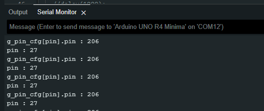
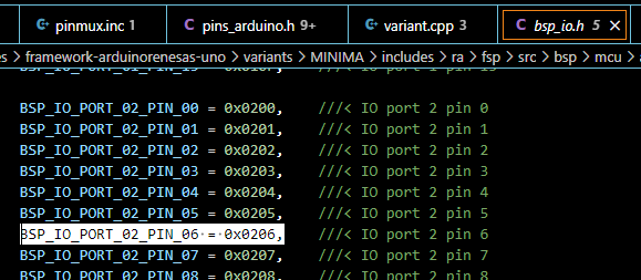
So I printed pin and g_pin_cfg[pin].pin for both digitalRead and pinMode and I get the right values for both P214 and P215 bsp_io.h address :
For P215 (206 in HEX format)
So I’m still thinking that the key is to write the right code for P214 and P215 in the pinmux.inc file.
I precise that when I try other port (already written in the pinmux file), I’m able to read input.
Huh? So Arduino-pin number 27 should be per
the P215, but the print shows that it’s the value for BSP_IO_PORT_02_06 instead? So that’s wrong then?
Sorry, my mistake.
I change it to (because P206 is already written in the pinmux file)
{ BSP_IO_PORT_02_PIN_06, P206 }, /* (27) DI100 */
only to compare (that is why I understand that I have to write the right code in pinmux , because I can read the P206 port without problem).
But both give righ pin result, its certain
Did you try writing a minimal sketch with the direct Renesas FSP APIs to check if you get the right results? If calling into those APIs still gives you the wrong result, it’s more likely to be a hardware than a software problem.
#include <Arduino.h>
#define INPUT_PIN BSP_IO_PORT_02_PIN_15
void setup() {
  R_IOPORT_PinCfg(NULL, INPUT_PIN, IOPORT_CFG_PORT_DIRECTION_INPUT);
  Serial.begin(115200);
}

void loop() {
  bsp_io_level_t ret;
  R_IOPORT_PinRead(NULL, INPUT_PIN, &ret);
  if(ret == BSP_IO_LEVEL_LOW) {
    Serial.println("Pin LOW");
  } else {
    Serial.println("Pin HIGH");
  }
  delay(500);
}
After trial, same result, it doesn’t works for P215 and P214, but it works for P206…
Is it possible that arduino minima bootloader doesn’t take into account those P214 and 215 pins ?
Okay, thank you for your helphttps://github.com/arduino/ArduinoCore-renesas/issues/160
Too bad I can’t understand how to write properly P214 and 215 in the pinmux.inc file
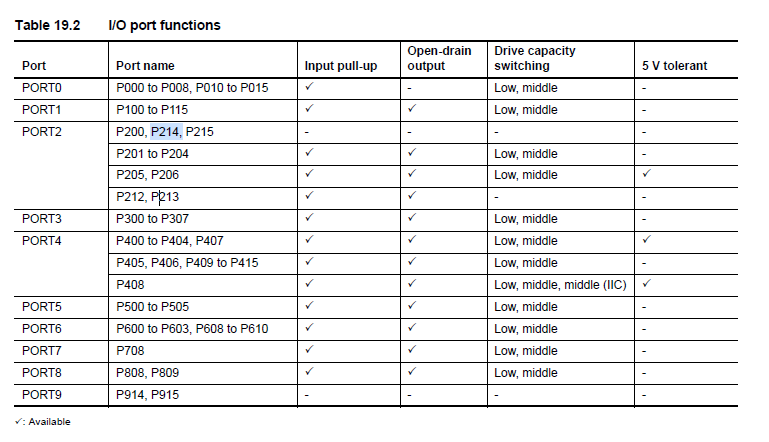
When I read this datasheet page
Can you confirm that we can’t actually read P214 and P215 port ?
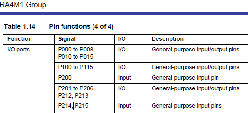
Because what’s not clear for me is that we can see also this p.61
I read this such that P214 and P215 can still be used in GPIO input mode normally. Just no input-pullup resistor available (so INPUT should work but not INPUT_PULLUP in pinMode()).
Okay, thanks.
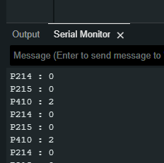
So I also tried to read directly to the P214 and 215 register, but nothing ! Still 0
#include <Arduino.h>


#define PORTBASE 0x40040000 /* Port Base */
#define P214 ((volatile unsigned char  *)(PORTBASE + 0x08B3 + (2 * 4)))
#define P215 ((volatile unsigned char  *)(PORTBASE + 0x08B3 + (3* 4)))
#define P410 ((volatile unsigned char  *)(PORTBASE + 0x0903 + (10* 4))) //
#define SOSCCR_SOSTP ((volatile unsigned char  *)(0x4001E480)) //


void setup(){
 Serial.begin(115200);
 *SOSCCR_SOSTP = 0x1; // datasheet p.137 et 362

}

void loop(){

Serial.print("P214 : ");
Serial.println(*P214);
Serial.print("P215 : ");
Serial.println(*P215);
Serial.print("P410 : ");
Serial.println(*P410);
delay(1000);

}