Un ROV de agua dulce / A sweet water ROV

Este es el programa llamado Esclavo, que es el que esta dentro del vehículo, pongo primero la cabecera con las explicaciones, y después el código.

This is the program called Slave, which is the one inside the vehicle, I put first the header with the explanations, and then the code.

/*
  Modificado por asesorplaza1 en las diferentes fechas indicadas
  Las primeras pruebas y cambios del código, se iniciaron en 2.016, debido a la cantidad de modificaciones
  A partir de ahora 30/01/2020, se ponen las fechas y los cambios en la descripción del proyecto
  Para facilitar la búsqueda de errores en los diferentes cambios del código

  30/01/2020 ya se han comentado todas las líneas de control de la cámara y del LCD
  Le añado 2 DHT22 y así estarán los 3 que me hacen falta
  He borrado varias líneas de control de la cámara que no se va a utilizar

  01/02/2020 le añado los controles del giroscopio facilitados por Dea de www.cambatronics.com

  02/02/2020 le añado la orden para leer solo 1 vez X segundo el DHT22, truco de José Luis de
  www.cambatronics.com
  y se borran las líneas correspondientes al control de la cámara de video
  No utilizadas por asesorplaza1, en esta modificación del proyecto original

  04/02/2020 modifico las líneas de lectura de los sensores, porque hasta ahora solo me imprime en Monitor Serie el texto, no los datos

  06/02/2020 se depura un poco el código, y se modifica el encabezado del código

  08/02/2020 se corrige el error de lectura en los sensores, y se corrige la escritura del Monitor Serie

  12/02/2020 para poder añadir cualquier código hay que seguir unas reglas especificas de programación
  Se modifica la estructura del código siguiendo esas órdenes de programación, según la información obtenida y guardada
  En la carpeta 01_UNIR_2_CODIGOS
  Se crean varios bloques en el void loop, para el funcionamiento de cada uno de los sensores, eliminando los delay()

  13/02/2020 se incluye el sensor de temperatura DS18B20, ayudado por DEA de www.cambatronics.com

  16/02/2020  Se añade el sensor de distancia infrarrojo E18-D80NK, sin errores
  y consigo adaptar un código para leer el sensor de presión SKU237545

  08/03/2020 se conecta un relé en el pin 12 del Arduino Esclavo, para encender los focos de luz externos, no hace falta cambiar el código

  26/03/2020 Se incluye la librería MPU6050, para controlar el giroscopio
  Se arregla el envió de datos, separando los datos del Monitor Serie, y los datos que hay que enviar al Arduino Maestro,
  iniciando dos puertos serie con las ordenes

  Serial.begin(57600);     // Puerto Serie USB

  Serial1.begin(57600);    // Puerto Serie en los pines 18 y 19

  ETin.begin(details(rxdata), &Serial1);    // Comienza la recepción de datos a través de Serial, en los pines 18 y 19

  ETout.begin(details(txdata), &Serial1);   // Comienza el envío de datos a través de Serial, en los pines 18 y 19

  28/03/2020 Se incluyen el envió de todas las instrucciones del mando, para tener todos los botones operativos (no funciona)

  03/04/2020 Se incluye la parte nueva del Giroscopio MPU6050, que muestra los 3 ejes de inclinación, más la temperatura del Giroscopio.
  Se incluye el segundo sensor de presión

  05/04/2020 se cambia el código del sensor infrarrojo E18D80NK, por uno mejor

  11/04/2020 Corrijo el código según las instrucciones de mi amigo Atilano Belinchón

  13/04/2020 Corrijo las lecturas y envió de datos del sensor de infrarrojos E18D80NK

  15/04/2020 Se incluye el servo de dirección para accionarlo con los botones R1 y R2 del mando
  según información obtenida de la pagina

  https://arduparatodos.blogspot.com/2017/02/controlar-servomotor-con-arduino-varios.html

  18/04/2020 Se cambian algunos " if ", por " else if ", para darle agilidad al código, siguiendo las instrucciones de DEA de www.cambatronics.com

  Entre el día 24/03/2020 y el día 28/04/2020, se hacen varios cambios en el código para mejorarlo y conseguir que el mando funcione,
  Siguiendo las instrucciones de bigbadbob en las publicaciones del foro

  http://www.homebuiltrovs.com/rovforum/viewtopic.php?f=18&t=1908

  A partir de la página 4

  28/04/2020 Se corrige la ortografía de todo le texto que no son órdenes

  03/05/2020 Se cambian las asignaciones de los pines, según el código de Github

  Las nuevas asignaciones de pines son:

  Salida de 3.3V a PIN rojo PS2
  Pin 24 a PIN amarillo PS2 + resistencia 1k
  Pin 23 a PIN naranja PS2
  Pin 25 a PIN marrón PS2 + resistencia 1k
  Pin 22 a PIN azul PS2

  Se arregla el código para que me salga en el Maestro el estado de los focos, encendidos / apagados

  04/05/2020 Se depura el código según los consejos de Bigbadbob de http://www.homebuiltrov.com

  05/05/2020 Se incluye la Macro F, en todos los Serial.print, para reducir el consumo de memoria dinámica
  Según los consejos de Bigbadbob de http://www.homebuiltrov.com, pero me da problemas

  06/05/2020 Se depura el código para un mejor funcionamiento, según los consejos de Bigbadbob de http://www.homebuiltrov.com
  y siguen los problemas con la Macro F

  07/05/2020 Se depura el código para un mejor funcionamiento, según los consejos de Bigbadbob de http://www.homebuiltrov.com
  y siguen los problemas con la Macro F

  08/05/2020 Se corrigen los problemas de la Macro F, en todos los Serial.print de texto fijo
  No se puede poner la Macro F, a los Serial.print de datos de los sensores
  Y se consigue reducir el consumo de memoria dinámica considerablemente

  09/05/2020 Se siguen corrigiendo líneas para la depuración del código, según los consejos de Bigbadbob de http://www.homebuiltrov.com
  Pero siguen los problemas con el mando de la PS2

  10/05/2020 Me doy cuenta de un error en la orden de encender los focos y lo corrijo
  Pero el mando sigue sin funcionar como es debido

  11/05/2020 Se modifican varias órdenes del control de los botones, pero el mando sigue sin funcionar correctamente

  16/05/2020 Se hacen diversos cambios, segun los consejos de Tsanshon de www.foromodelismonaval.es


  La versión original tomada como punto de partida es la siguiente

  ROVPS2Control_Slavev8.ino
  Hamish Trolove - 30 de marzo de 2016
  www.techmonkeybusiness.com

  Este boceto toma los comandos que se le envían desde la unidad maestra con el controlador PS2 conectado y lo convierte en comandos de motor,
  Servo comandos, controles de luz, etc. Los datos se envían desde el Arduino (maestro) al ROV (esclavo) utilizando la biblioteca EasyTransfer de Bill Porter a través de un enlace en serie de 9600 baudios (anclaje de 100 m). La biblioteca MS5803_14 es de Luke Miller http://github.com/millerlp

  Los datos enviados desde el maestro son configuraciones sin formato para el control ESC.

  Este boceto está diseñado para un Arduino Nano con un solo puerto serie.

  Yo lo estoy usando en un Mega 2560, y funcionba, hasta que empecé a introducir sensores


  Para la transmisión del video asesorplaza1 utilizara una Raspberry Pi 3 plus, una cámara USB, y el programa VCL Media Player

  Se cambian estos sensores por obsoletos, se usan los sensores DHT22 y el giroscopio MPU6050

  Conexión serial de comunicaciones: modificado por Asesorplaza1, el 26/03/2020, para separar los datos mandados entre Arduinos, de los datos a mandar al Monitor serie
  19 superior (TX) a ROV 18 (RX) Conexión serial: 18 superior (RX) a ROV 19 (TX)
  Conecte el GND en ambos

  Tenga en cuenta que los ESC ya se habrán programado en este punto del proyecto.

  Los datos de voltaje interno, rumbo, profundidad y temperatura interna se envían a través del enlace serie de regreso al maestro
  Para su visualización en una pantalla LCD de 16x2.
  La pantalla LCD de 16x2, se cambiara por una pantalla Nextion básica de 5"

  Se cambia este sensor por obsoleto, se usa el giroscopio MPU 6050

  Ver también como se desarrolla el proyecto original con los siguientes códigos:
  HoryzonTrigger.ino, ROVPS2Control_Masterv0.ino,
  ROVDoNothing.ino, ROVSubBv0.ino, DigitalCompassv2.ino,
  PTLoggerv4.ino y TMP36_Temperature_Sensor.ino.
  En la página www.techmonkeybusiness.com

*/

/*
Modified byplaza advisor1 on the different dates indicated
The first tests and code changes were initiated in 2,016, due to the number of modifications
As of now 30/01/2020, dates and changes are made to the project description
To make it easier to find errors in different code changes

30/01/2020 all camera and LCD control lines have already been commented on
I add 2 DHT22 and so will be the 3 I need
I've erased several control lines from the camera that won't be used

01/02/2020 I add the gyroscope controls provided by Dea de [www.cambatronics.com](https://ssl.microsofttranslator.com/bv.aspx?ref=TAns&from=&to=en&a=www.cambatronics.com)

02/02/2020 I add the order to read only 1 time X second the DHT22, trick by José Luis de
[www.cambatronics.com](https://ssl.microsofttranslator.com/bv.aspx?ref=TAns&from=&to=en&a=www.cambatronics.com)
and the lines corresponding to the control of the video camera are deleted
Not used byplaza advisor1, in this modification of the original project

04/02/2020 I modify the reading lines of the sensors, because so far I only print in Monitor Series the text, not the data

06/02/2020 debugging the code a bit, and modifying the code header

08/02/2020 corrects the reading error in the sensors, and corrects the writing of the Series Monitor

12/02/2020 to be able to add any code you have to follow specific programming rules
The structure of the code is modified according to those programming orders, based on the information obtained and stored
In the 01_UNIR_2_CODIGOS folder
Several blocks are created in the void loop, for the operation of each of the sensors, eliminating the delay()

13/02/2020 temperature sensor DS18B20 is included, assisted by DEA of [www.cambatronics.com](https://ssl.microsofttranslator.com/bv.aspx?ref=TAns&from=&to=en&a=www.cambatronics.com)

16/02/2020 E18-D80NK infrared distance sensor added, no errors
and I get to adapt a code to read the pressure sensor SKU237545

08/03/2020 a relay is connected on pin 12 of the Arduino Slave, to turn on the external light bulbs, there is no need to change the code

26/03/2020 The MPU6050 library is included to control the gyroscope
Fixed data sending, separating the data from the Serial Monitor, and the data to be sent to the Arduino Maestro,
initiating two serial ports with orders

Serial.begin(57600); USB Series Port

Serial1.begin(57600); Serial port on pins 18 and 19

ETin.begin(details(rxdata), &Serial1); Data reception begins through Serial, at pins 18 and 19

ETout.begin(details(txdata), &Serial1); Start sending data through Serial, at pins 18 and 19

28/03/2020 All control instructions are included, to have all buttons operational (not working)

03/04/2020 The new part of the MPU6050 Gyroscope is included, showing the 3 tilt axes, plus the temperature of the Gyroscope.
Included is the second pressure sensor

05/04/2020 the code of the infrared sensor E18D80NK is changed, to a better one

11/04/2020 I correct the code according to the instructions of my friend Atilano Belinchón

13/04/2020 I correct the readings and send data from the E18D80NK infrared sensor

15/04/2020 Steering servo is included to operate it with the R1 and R2 buttons on the controller
based on information obtained from the website

[https://arduparatodos.blogspot.com/2017/02/controlar-servomotor-con-arduino-varios.html](https://ssl.microsofttranslator.com/bv.aspx?ref=TAns&from=&to=en&a=https%3A%2F%2Farduparatodos.blogspot.com%2F2017%2F02%2Fcontrolar-servomotor-con-arduino-varios.html)

18/04/2020 Some "if" are changed to "else if" to give the code agility, following the DEA instructions in [www.cambatronics.com](https://ssl.microsofttranslator.com/bv.aspx?ref=TAns&from=&to=en&a=www.cambatronics.com)

Between 24/03/2020 and 28/04/2020, several code changes are made to improve it and make the controller work,
Following the instructions of bigbadbob in the forum posts

[http://www.homebuiltrovs.com/rovforum/viewtopic.php?f=18&t=1908](https://ssl.microsofttranslator.com/bv.aspx?ref=TAns&from=&to=en&a=http%3A%2F%2Fwww.homebuiltrovs.com%2Frovforum%2Fviewtopic.php%3Ff%3D18%26t%3D1908)

From page 4

28/04/2020 Corrects the spelling of all text that are not orders

03/05/2020 Pin assignments are changed, according to Github code

The new pin assignments are:

3.3V output to red PS2 PIN
Pin 24 to PS2 yellow PIN + 1k resistance
Pin 23 to PIN Orange PS2
Pin 25 to PIN brown PS2 + 1k resistance
Pin 22 to PS2 Blue PIN

Fixed the code to get me out in the Master the state of the spotlights, on/off

04/05/2020 Code is debugged according to Bigbadbob's advice from [http://www.homebuiltrov.com](https://ssl.microsofttranslator.com/bv.aspx?ref=TAns&from=&to=en&a=http%3A%2F%2Fwww.homebuiltrov.com)

05/05/2020 Macro F is included, in all Serial.print, to reduce dynamic memory consumption
According to Bigbadbob's advice from http://www.homebuiltrov.com, but it gives me trouble

06/05/2020 Code is debugged for better performance, according to Bigbadbob's advice from [http://www.homebuiltrov.com](https://ssl.microsofttranslator.com/bv.aspx?ref=TAns&from=&to=en&a=http%3A%2F%2Fwww.homebuiltrov.com)
and the problems with Macro F follow

07/05/2020 Code is debugged for better performance, according to Bigbadbob's advice from [http://www.homebuiltrov.com](https://ssl.microsofttranslator.com/bv.aspx?ref=TAns&from=&to=en&a=http%3A%2F%2Fwww.homebuiltrov.com)
and the problems with Macro F follow

08/05/2020 Fixed Macro F issues in all fixed-text [Serial.prints](https://ssl.microsofttranslator.com/bv.aspx?ref=TAns&from=&to=en&a=Serial.prints)
You can't put Macro F, to [Serial.print](https://ssl.microsofttranslator.com/bv.aspx?ref=TAns&from=&to=en&a=Serial.print) sensor data
And it reduces dynamic memory consumption considerably

09/05/2020 Lines are still corrected for code debugging, according to Bigbadbob's advice from [http://www.homebuiltrov.com](https://ssl.microsofttranslator.com/bv.aspx?ref=TAns&from=&to=en&a=http%3A%2F%2Fwww.homebuiltrov.com)
But the problems with PS2 command continue

10/05/2020 I notice an error in the order to turn on the spotlights and correct it
But the controller still doesn't work properly

11/05/2020 Several button control commands are modified, but the controller still does not work properly

16/05/2020 Various changes are made, according to Tsanshon's advice from [www.foromodelismonaval.es](https://ssl.microsofttranslator.com/bv.aspx?ref=TAns&from=&to=en&a=www.foromodelismonaval.es)

The original version taken as a starting point is as follows

ROVPS2Control_Slavev8.ino
Hamish Trolove - 30 March 2016
[www.techmonkeybusiness.com](https://ssl.microsofttranslator.com/bv.aspx?ref=TAns&from=&to=en&a=www.techmonkeybusiness.com)

This sketch takes the commands that are sent to you from the master drive with the PS2 controller connected and converts it to engine commands,
Servo commands, light controls, etc. The data is sent from the Arduino (master) to the ROV (slave) using Bill Porter's EasyTransfer library via a 9600 baud (100 m anchor) serial link. The MS5803_14 library is by Luke Miller [http://github.com/millerlp](https://ssl.microsofttranslator.com/bv.aspx?ref=TAns&from=&to=en&a=http%3A%2F%2Fgithub.com%2Fmillerlp)

Data sent from the master are raw configurations for the ESC control.

This sketch is designed for an Arduino Nano with a single serial port.

I'm using it on a Mega 2560, and it worked, until I started introducing sensors

For the transmission of the video advisorplaza1 will use a Raspberry Pi 3 plus, a USB camera, and the program VCL Media Player

These sensors are changed to obsolete, dhT22 sensors and the MPU6050 gyroscope are used

Serial communications connection: modified by Adviserplaza1, 26/03/2020, to separate the data sent between Arduinos, from the data to be sent to the Serial Monitor
19 top (TX) to ROV 18 (RX) Serial connection: 18 top (RX) to ROV 19 (TX)
Connect the GND on both

Note that THE ESCs have already been scheduled at this point in the project.

Internal voltage, heading, depth, and internal temperature data are sent via the series link back to the master
For viewing on a 16x2 LCD screen.
The 16x2 LCD display will be replaced by a basic Nextion display of 5"

This sensor is changed to obsolete, the MPU 6050 gyroscope is used

See also how the original project develops with the following codes:
HoryzonTrigger.ino, ROVPS2Control_Masterv0.ino,
ROVDoNothing.ino, ROVSubBv0.ino, DigitalCompassv2.ino,
[PTLoggerv4.ino](https://ssl.microsofttranslator.com/bv.aspx?ref=TAns&from=&to=en&a=PTLoggerv4.ino) and TMP36_Temperature_Sensor.ino.
On the [www.techmonkeybusiness.com](https://ssl.microsofttranslator.com/bv.aspx?ref=TAns&from=&to=en&a=www.techmonkeybusiness.com) page

*/
// Se ponen todas las librerías juntas
#include <Servo.h>              // librería para gestionar los servos y los ESC
#include <EasyTransfer.h>       // librería Easy Transfer de Bill Porter
#include <Adafruit_Sensor.h>    // librería para gestionar el sensor de temperatura DHT22
#include <DHT.h>                // librería para el sensor DHT 22
#include <OneWire.h>            // librería para el sensor de temperatura DS18B20
#include <DallasTemperature.h>  // Librería para el sensor de temperatura DS18B20
#include <MPU6050.h>            // librería i2c para el Giroscopio ***
#include <PS2X_lib.h>           // Librería para el mando PS2
#include <ESC.h>                // Librería para los ESC

PS2X ps2x;                          // Genera un objeto llamado ps2x
EasyTransfer ETin, ETout;           // Genera los dos objetos de transferencia fácil para Comunicación bidireccional

const int pinDatosDQ = 28;                       // Pin donde se conecta el bus 1-Wire para los sensores de temperatura
OneWire oneWireObjeto(pinDatosDQ);               // Instancia a las clases OneWire y DallasTemperature
DallasTemperature sensorDS18B20(&oneWireObjeto); // Instancia a las clases OneWire y DallasTemperature

// #define F(string_literal) (reinterpret_cast<const __FlashStringHelper *>(PSTR(string_literal)))

// Se pone toda la identificación de los DHT22 junta

DHT dht(22, DHT22);    // Seleccionamos el pin y tipo de sensor del casco
DHT dht1(24, DHT22);   // Seleccionamos el pin y tipo de sensor del motor derecho
DHT dht2(26, DHT22);   // Seleccionamos el pin y tipo de sensor del motor izquierdo

// Se pone toda la identificación de los ESC y los Servos junta

ESC ESCVL(8, 1000, 2000, 500);           // Genera objeto ESC vertical izquierdo en el pin 8, con el minimo en 1000, maximo en 2000, y armado en 500
ESC ESCVR(7, 1000, 2000, 500);           // Genera objeto ESC vertical derecho en el pin 7, con el minimo en 1000, maximo en 2000, y armado en 500
ESC ESCHL(6, 1000, 2000, 500);           // Genera Objeto ESC Horizontal Izquierdo en el pin 6, con el minimo en 1000, maximo en 2000, y armado en 500
ESC ESCHR(5, 1000, 2000, 500);           // Genera objeto ESC Horizontal Derecho, en el pin 5, con el minimo en 1000, maximo en 2000, y armado en 500
Servo ServoInmersion;           // Genera un objeto llamado ServoDireccion
int angulo = 90;                // Variable para el ángulo, inicia en 90º

// Se pone toda la identificación de los LED indicadores de batería junta

const int RedLEDpin = 13;  // El pin del indicador LED es 13.
const int HeadLts = 34;    // El control de los faros está en el pin 34
const int Voltpin = A7;    // pin analógico utilizado para leer el voltaje de la batería
const int yelLEDpin = 38;  // Pin utilizado como chivato de recibir datos del mando

// Se pone toda la identificación del sistema de refrigeración junta

const int Refrigeracion = 34; // el pin utilizado para encender la bomba de refrigeración es el 34
const int TwarnLEDpin = 36;   // El pin utilizado para el LED de alarma de temperatura es el 36

// Se pone toda la identificación del MPU6050 junta

const int MPU6050_addr = 0x68; // Direction I2C del MPU6050
int16_t AccX, AccY, AccZ, Temp, GyroX, GyroY, GyroZ;

// Se pone toda la parte de lectura de la batería junta

int volts;                          // variable para leer el voltaje del pin analógico
const float RefVolts = 5.0;         // Voltaje de referencia de la placa de 5 voltios en Nano
const float ResistFactor = 319.68;  // Calculado a partir de 1023.0 * (R2 / (R1 + R2)
// Donde R1 = 2200 ohmios y R2 = 1000 ohmios para un voltaje máximo de 15 V.

// Se pone toda la parte del sensor E18D80NK

int pinSensorE18D80NK = 30;   // Se genera el sensor E18D80NK en el pin 30
int pinLedColision = 31;      // Se genera el LED de aviso de peligro colisión en el pin 31
boolean objectDetect = false; // Marca para mostrar si se ha detectado un objeto

// Se generan todos los botones del mando

boolean PSB_PAD_UPstate = false;     // Genera el botón Izquierda arriba al Esclavo
boolean PSB_PAD_DOWNstate = false;   // Genera el botón Izquierda abajo al Esclavo
boolean PSB_PAD_LEFTstate = false;   // El botón Izquierda izquierdo ya esta usado para encender los focos
boolean PSB_PAD_RIGHTstate = false;  // Genera el botón Izquierda derecho al Esclavo
boolean PSB_BLUEstate = false;       // Genera el botón Cruz azul al Esclavo
boolean PSB_GREENstate = false;      // Genera el botón Triangulo verde al Esclavo
boolean PSB_PINKstate = false;       // Genera el botón Cuadrado rosa al Esclavo
boolean PSB_REDstate = false;        // Genera el botón Circulo rojo al Esclavo
boolean PSB_L1state = false;         // Genera el botón Izquierda delante arriba al Esclavo
boolean PSB_L2state = false;         // Genera el botón Izquierda delante abajo al Esclavo
boolean PSB_L3state = false;         // Genera el botón Palo izquierdo abajo al Esclavo
boolean PSB_R1state = false;         // Genera el botón Derecha delante arriba al Esclavo
boolean PSB_R2state = false;         // Genera el botón Derecha delante abajo al Esclavo
boolean PSB_R3state = false;         // Genera el botón Palo derecho abajo al Esclavo

// Se genera un pin de entrada de datos para el sensor de presión SKU237545

int SensorSKU237545_I = 32;  // Sensor de presión Interno
int SensorSKU237545_E = 33;  // Sensor de presión Externo

int intervalodatos = 1000;  // Hace que solo se envíen los valores 1 vez por segundo
// int auxMillis = 0;          // Indica el valor del intervalo de tiempo

// Se pone toda la estructura de recepción de datos junta

struct RECEIVE_DATA_STRUCTURE {
  int upLraw = 0;   // Variables para transportar los datos sin procesar reales de los ESC
  int upRraw = 0;
  int HLraw = 0;
  int HRraw = 0;
  volatile boolean PSB_PAD_UPstate;     // Recibe lectura del botón Izquierda arriba del Maestro
  volatile boolean PSB_PAD_DOWNstate;   // Recibe lectura del botón Izquierda abajo del Maestro
  volatile boolean PSB_PAD_RIGHTstate;  // Recibe lectura del botón Izquierda derecha del Maestro
  volatile boolean PSB_PAD_LEFTstate;   // Recibe lectura del botón Izquierda Izquierda del Maestro
  volatile boolean PSB_BLUEstate;       // Recibe lectura del botón Cruz azul del Maestro
  volatile boolean PSB_GREENstate;      // Recibe lectura del botón Triangulo verde del Maestro
  volatile boolean PSB_PINKstate;       // Recibe lectura del botón Cuadrado rosa del Maestro
  volatile boolean PSB_REDstate;        // Recibe lectura del botón Circulo rojo del Maestro
  volatile boolean PSB_L1state;         // Recibe lectura del botón Delante izquierda arriba del Maestro
  volatile boolean PSB_L2state;         // Recibe lectura del botón Delante izquierda abajo del Maestro
  volatile boolean PSB_L3state;         // Recibe lectura de presión Palo izquierda del Maestro
  volatile boolean PSB_R1state;         // Recibe lectura del botón Delante derecha arriba del Maestro
  volatile boolean PSB_R2state;         // Recibe lectura del botón Delante derecha abajo del Maestro
  volatile boolean PSB_R3state;         // Recibe lectura de presión Palo izquierdo del Maestro
  volatile boolean LEDHdlts;            // Luces LED encendidas / apagadas
};

// Se pone toda la identificación del envío de datos junta

struct  SEND_DATA_STRUCTURE {
  int BattVolt;             // Manda mensaje de datos de voltaje de batería al maestro.
  int t;                    // Manda mensaje de datos de temperatura interior del ROV al Maestro
  int t1;                   // Manda mensaje de datos de temperatura del motor derecho al Maestro
  int t2;                   // Manda mensaje de datos de temperatura del motor izquierdo al Maestro
  int ROVDepth;             // Manda mensaje de datos de lectura de profundidad de ROV (m)
  int ROVHDG;               // Manda mensaje de Dirección del ROV (grados)
  int h;                    // Manda mensaje de humedad al Maestro
  int h1;                   // Manda mensaje de humedad al Maestro del motor derecho
  int h2;                   // Manda mensaje de humedad al Maestro del motor izquierdo
  int AccX;                 // Manda mensaje de datos de inclinación del eje X al Maestro
  int AccY;                 // Manda mensaje de datos de inclinación del eje Y al Maestro
  int AccZ;                 // Manda mensaje de datos de de inclinación del eje Z al Maestro
  int Temp;                 // Manda mensaje de datos de temperatura del giroscopio al Maestro
  int GyroX;                // Manda mensaje de datos de aceleración en el eje X al Maestro
  int GyroY;                // Manda mensaje de datos de aceleración en el eje Y al Maestro
  int GyroZ;                // Manda mensaje de datos de aceleración en el eje Z al Maestro
  int E18D80NK;             // Manda mensaje de lectura del sensor infrarrojo E18-D80NK
  int pinLedColision;       // Manda mensaje de encender alarma de colisión
  int sensorDS18B20;        // Manda mensaje de lectura del sensor de temperatura DS18B20
  int pressure_bar;         // Manda mensaje de lectura del sensor de presión SKU237545 Interno en Bares
  int pressure_psi;         // Manda mensaje de lectura del sensor de presión SKU237545 Interno en PSI
  int pressure_bar1;        // Manda mensaje de lectura del sensor de presión SKU237545 Interno en Bares
  int pressure_psi1;        // Manda mensaje de lectura del sensor de presión SKU237545 Interno en PSI
};

RECEIVE_DATA_STRUCTURE rxdata; // Dar un nombre al grupo de datos recibidos
SEND_DATA_STRUCTURE txdata;    // Dar un nombre al grupo de datos enviados

void setup()
{

  // Se pone todo lo referente a la comunicación junta

  Wire.begin ();                           // Comienza la comunicación i2c

  Serial.begin(9600);                       // Comienza la Comunicación Serie para hablar con el ordenador a 9600 baudios
  Serial1.begin(9600);                     // Comienza la Comunicación Serie en el puerto 1, pines 18 y 19, para hablar con el Arduino Maestro
  Serial1.flush();                         // Depura la información del Puerto Serie
  ETin.begin(details(rxdata), & Serial1);  // Comienza la recepción de datos a través de Serial, en los pines 18 y 19
  ETout.begin(details(txdata), & Serial1); // Comienza el envío de datos a través de Serial, en los pines 18 y 19
  sensorDS18B20.begin();                   // Comienza el trabajo del sensor DS18B20

  // Se define el inicio del LED y de los Focos

  pinMode(RedLEDpin, OUTPUT);
  pinMode(HeadLts, OUTPUT);
  digitalWrite(HeadLts, LOW);  // Establezca los faros en Off
  digitalWrite(RedLEDpin, LOW);

  // Se inician los ESC y se define en que pin actúa cada uno
  ESCVL.arm();         // Inicia el ESCVL
  ESCVR.arm();         // Inicia el ESCVR
  ESCHL.arm();         // Inicia el ESCHL
  ESCHR.arm();         // Inicia el ESCHR

  // Esto hay que comprobarlo
  // Debido a problemas con el ESC que reconoce el máximo posición en la configuración predeterminada, las cifras después de
  // El número de pin son las señales de microsegundos para el mínimo y máximo que el ESC reconocerá, 600 y 2250 trabajo.

  ServoInmersion.attach(4); // Adjunte el servo de dirección al pin 4
  ServoInmersion.write(90); // Posiciona el servo inicialmente en la mitad (90°)

  // Se inician y se manda a imprimir la prueba de funcionamiento de los sensores DHT22
  dht.begin();  // Inicia el trabajo del sensor DHT22 del casco
  Serial.println (F(" \n Probando sensor DHT22 casco!"));
  dht1.begin(); // Inicia el trabajo del sensor DHT22 del motor derecho
  Serial.println (F(" \n Probando sensor DHT22 motor DR!"));
  dht2.begin(); // Inicia el trabajo del sensor DHT22 del motor izquierdo
  Serial.println (F(" \n Probando sensor DHT22 motor IZ!"));

  // Se inician los pines del sensor y de la alarma
  pinMode(pinSensorE18D80NK, INPUT_PULLUP); // Definir pin como sensor de entrada
  pinMode(pinLedColision, OUTPUT); // Definir pin como SALIDA para ACTION

  // Se inicia el pin del sensor de presión SKU237545 Interno
  pinMode (SensorSKU237545_I, INPUT);

  // Se inicia el pin del sensor de presión SKU237545 Externo
  pinMode (SensorSKU237545_E, INPUT);

  // Proceso para iniciar el giroscopio MPU6050
  Wire.begin();
  Wire.beginTransmission(MPU6050_addr);
  Wire.write(0x6B);
  Wire.write(0);
  Wire.endTransmission(true);

  delay (200);
}

void loop ()
{

  if (ETin.receiveData());    // Recibe los datos al puerto serie para el ROV
  {
    Serial.print (F("\n Datos recibidos del Meastro.."));
  }
  loop_ESC();             // Bloque de trabajo de los ESC de los motores
  loop_Luces();           // Bloque de trabajo de los focos
  loop_Voltaje();         // Bloque de trabajo para medir el voltaje de la batería
  loop_DHT22();           // Bloque de trabajo de los sensores de temperatura y humedad DHT22
  loop_MPU6050();         // Bloque de trabajo del Giroscopio
  loop_SensorE18D80NK();  // Bloque de trabajo del sensor de infrarrojos
  loop_DS18B20();         // Bloque de trabajo del sensor de temperatura DS18B20
  loop_SKU237545_I();     // Bloque de trabajo del sensor de presión interno
  loop_SKU237545_E();     // Bloque de trabajo del sensor de presión externo
  loop_ServoInmersion();  // Bloque de trabajo del servo

  PSB_PAD_UPstate = (rxdata.PSB_PAD_UPstate);         // Recibe lectura del botón Izquierda arriba al Esclavo
  PSB_PAD_DOWNstate = (rxdata.PSB_PAD_DOWNstate);     // Recibe lectura del botón Izquierda abajo al Esclavo
  PSB_PAD_LEFTstate = (rxdata.PSB_PAD_LEFTstate);     // Recibe lectura del botón Izquierda Izquierda al Esclavo
  PSB_PAD_RIGHTstate = (rxdata.PSB_PAD_RIGHTstate);   // Recibe lectura del botón Izquierda derecho al Esclavo
  PSB_BLUEstate = (rxdata.PSB_BLUEstate);             // Recibe lectura del botón Cruz azul al Esclavo
  PSB_GREENstate = (rxdata.PSB_GREENstate);           // Recibe lectura del botón Triangulo verde al Esclavo
  PSB_PINKstate = (rxdata.PSB_PINKstate);             // Recibe lectura del botón Cuadrado rosa al Esclavo
  PSB_REDstate = (rxdata.PSB_REDstate);               // Recibe lectura del botón Circulo rojo al Esclavo
  PSB_L1state = (rxdata.PSB_L1state);                 // Recibe lectura del botón Izquierda delante arriba al Esclavo
  PSB_L2state = (rxdata.PSB_L2state);                 // Recibe lectura del botón Izquierda delante abajo al Esclavo
  PSB_L3state = (rxdata.PSB_L3state);                 // Recibe lectura del botón Palo izquierdo abajo al Esclavo
  PSB_R1state = (rxdata.PSB_R1state);                 // Recibe lectura del botón Derecha delante arriba al Esclavo
  PSB_R2state = (rxdata.PSB_R2state);                 // Recibe lectura del botón Derecha delante abajo al Esclavo
  PSB_R3state = (rxdata.PSB_R3state);                 // Recibe lectura del botón Palo derecho abajo al Esclavo

  // No me deja generar un bloque de trabajo para los botones del mando
  // Por eso los pongo dentro del void loop genérico

  if (rxdata.PSB_PAD_UPstate)
    // Si presionamos el botón izquierda arriba
  {
    digitalWrite(yelLEDpin, HIGH);
    // Enciende el Led Amarillo
  }

  if (rxdata.PSB_PAD_DOWNstate)
    // Si presionamos el botón izquierda abajo
  {
    digitalWrite(yelLEDpin, HIGH);
    // Enciende el Led Amarillo
  }

  if (rxdata.PSB_PAD_RIGHTstate)
    // Si presionamos el botón izquierda derecha
  {
    digitalWrite(yelLEDpin, HIGH);
    // Enciende el Led Amarillo
  }

  if (rxdata.PSB_GREENstate)
    // Si presionamos triangulo verde
  {
    digitalWrite(yelLEDpin, HIGH);
    // Enciende el Led Amarillo
  }

  if (rxdata.PSB_REDstate)
    // Si presionamos el círculo rojo
  {
    digitalWrite(yelLEDpin, HIGH);
    // Enciende el Led Amarillo
  }

  if (rxdata.PSB_BLUEstate)
    // Si presionamos el cruz azul
  {
    digitalWrite(yelLEDpin, HIGH);
    // Enciende el Led Amarillo
  }

  if (rxdata.PSB_PINKstate)
    // Si presionamos el cuadrado rosa
  {
    digitalWrite(yelLEDpin, HIGH);
    // Enciende el Led Amarillo
  }

  if (rxdata.PSB_L1state)
    // Si presionamos el botón L1
  {
    digitalWrite(yelLEDpin, HIGH);
    // Enciende el Led Amarillo
  }

  if (rxdata.PSB_L2state)
    // Si presionamos el botón L2
  {
    digitalWrite(yelLEDpin, HIGH);
    // Enciende el Led Amarillo
  }

  if (rxdata.PSB_R1state)
    // Si presionamos el botón R1
  {
    // Enciende / apaga las luces
    digitalWrite(yelLEDpin, HIGH);
    // Enciende el Led Amarillo
  }

  if (rxdata.PSB_R2state)
    // Si presionamos el botón R2
  {
    // Enciende / apaga las luces
    digitalWrite(yelLEDpin, HIGH);
    // Enciende el Led Amarillo
  }

  if (rxdata.PSB_L3state)
    // Si presionamos el joystick izquierdo hacia abajo
  {
    digitalWrite(yelLEDpin, HIGH);
    // Enciende el Led Amarillo
  }

  if (rxdata.PSB_R3state)
    // Si presionamos el joystick derecho hacia abajo
  {
    digitalWrite(yelLEDpin, HIGH);
    // Enciende el LED Amarillo
  }

}

void loop_ESC() { // Bloque de trabajo de los ESC de los motores

  // Haremos algo correctamente con los datos devueltos en un
  ESCVL.speed(rxdata.upLraw);   // Establezca la señal ESCVL en la posición del acelerador definida.
  ESCVR.speed(rxdata.upRraw);   // Establezca la señal ESCVR en la posición del acelerador definida.
  ESCHL.speed(rxdata.HLraw);    // Establezca la señal ESCHL en la posición del acelerador definida.
  ESCHR.speed(rxdata.HRraw);    // Establezca la señal ESCHR en la posición del acelerador definida.

}

void loop_ServoInmersion() {         // Bloque de trabajo del Servo de Inmersión

  if (rxdata.PSB_R1state == LOW)
    // Aumenta el ángulo mientras se mantenga presionado
  {
    angulo++;
    if (angulo >= 180)
    {
      angulo = 180;
      // El ángulo no aumenta más allá de 180 grados
      Serial.print (F(" \n Subiendo ROV a superficie "));
    }
  }
  else if (rxdata.PSB_R2state == LOW)
    // Disminuye el ángulo mientras se mantenga presionado
  {
    angulo--;
    if (angulo <= 0)
    {
      angulo = 0;
      // El ángulo no disminuye mas allá de 0 grados
      Serial.print (F("\n Inmersion ROV a profundidad "));
    }
  }
  ServoInmersion.write(angulo);
  // Manda el ángulo al servo dependiendo del pulsador presionado
  //  delay(10);
}

void loop_Luces() { // Bloque de trabajo de los focos
  digitalWrite(HeadLts, rxdata.LEDHdlts);
  // Enciende los faros en función del retraso de los datos del mensaje
  if (rxdata.LEDHdlts > 0) {
    digitalWrite(HeadLts, LOW);
    Serial.print (F(" \n Focos apagados "));
  }
  else {
    (rxdata.LEDHdlts < 0);
    digitalWrite(HeadLts, HIGH);
    Serial.print (F(" \n Focos encendidos "));
  }
}

void loop_Voltaje() { // Bloque de trabajo de medición de voltaje de la batería

  volts = analogRead(Voltpin) / ResistFactor * RefVolts * 10; // Lee el voltaje
  // De la batería a través del divisor de voltaje. Factor de 10 utilizado
  // Para ayudar a lograr un número entero con una precisión de 0.1V.
  // Factor 10 utilizado para obtener precisión adicional del valor entero y luego se muestra con 1 decimal
  txdata.BattVolt = volts;  // Enviar de vuelta el voltaje de la batería a bordo.
  Serial.print (F(" \n Voltaje del ROV = "));
  Serial.print(volts);

}

void loop_DHT22() { // Bloque de trabajo de los sensores DHT22

  float h = dht.readHumidity();
  // Lectura de Humedad desde el sensor DHT22 del interior del ROV
  float t = dht.readTemperature();
  // Lectura de Temperatura desde el sensor DHT22 del interior del ROV
  float h1 = dht1.readHumidity();
  // Lectura de Humedad desde el sensor DHT22 del motor derecho
  float t1 = dht1.readTemperature();
  // Lectura de Temperatura desde el sensor DHT22 del motor derecho
  float h2 = dht2.readHumidity();
  // Lectura de Humedad desde el sensor DHT22 del motor izquierdo
  float t2 = dht2.readTemperature();
  // Lectura de Temperatura desde el sensor DHT22 del motor izquierdo
  int intervaloMedidas = 1000;
  // Hace que solo se lean los valores 1 vez por segundo
  unsigned long auxMillis = 0;
  // Indica el valor del intervalo de tiempo

  // Comprueba si hay fallo en todas las lecturas y sale rápido y prueba otra vez
  if (isnan(h) || isnan(t)) {
    Serial.print (F(" \n Fallo de lectura desde el sensor DHT del Casco!"));
    return;
  }
  else if (isnan(h1) || isnan(t1)) {
    Serial.print (F(" \n Fallo de lectura desde el sensor DHT del motor DR!"));
    return;
  }
  else if (isnan(h2) || isnan(t2)) {
    Serial.print (F(" \n Fallo de lectura desde el sensor DHT del motor IZ!"));
    return;
  }
  else if (( millis() - auxMillis) > intervaloMedidas) {
    txdata.t = t;   // Envía al Maestro la temperatura leída en el casco
    txdata.h = h;   // Envía al Maestro la humedad leída en el casco
    txdata.t1 = t1; // Envía al Maestro la temperatura leída en el motor derecho
    txdata.h1 = h1; // Envía al Maestro la humedad leída en el motor derecho
    txdata.t2 = t2; // Envía al Maestro la temperatura leída en el motor izquierdo
    txdata.h2 = h2; // Envía al Maestro la humedad leída en el motor izquierdo
    auxMillis = millis();
  }
  else if (t > 40 || t1 > 40 || t2 > 40)
  {
    // Si la temperatura de cualquiera de los sensores DHT22 es demasiado alta (más de 40 grados C)
    // Enciende el LED de advertencia
    digitalWrite(TwarnLEDpin, HIGH);
    // Enciende la bomba de refrigeración
    digitalWrite(Refrigeracion, HIGH);
    // Escribe el texto
    Serial.print (F(" \n TEMPERATURA ELEVADA !"));
  }
  Serial.print (F(" \n Temperatura en el casco = "));
  Serial.print (t);
  Serial.print (F(" *C "));
  Serial.print (F(" \n Temperatura en el motor DR = "));
  Serial.print (t1);
  Serial.print (F(" *C1 "));
  Serial.print (F(" \n Temperatura en el motor IZ = "));
  Serial.print (t2);
  Serial.print (F(" *C2 "));
  Serial.print (F(" \n Humedad en el Casco = "));
  Serial.print (h);
  Serial.print (F(" %\t"));
  Serial.print (F(" \n Humedad en el motor DR = "));
  Serial.print (h1);
  Serial.print (F(" %\t"));
  Serial.print (F(" \n Humedad en el motor IZ = "));
  Serial.print (h2);
  Serial.print (F(" %\t"));

}

void loop_MPU6050() {  // Bloque de trabajo del giroscopio

  Wire.beginTransmission(MPU6050_addr);
  Wire.write(0x3B);
  Wire.endTransmission(false);
  Wire.requestFrom(MPU6050_addr, 14, true);
  AccX = Wire.read() << 8 | Wire.read();
  AccY = Wire.read() << 8 | Wire.read();
  AccZ = Wire.read() << 8 | Wire.read();
  Temp = Wire.read() << 8 | Wire.read();
  GyroX = Wire.read() << 8 | Wire.read();
  GyroY = Wire.read() << 8 | Wire.read();
  GyroZ = Wire.read() << 8 | Wire.read();

  txdata.AccX = AccX;
  txdata.AccY = AccY;
  txdata.AccZ = AccZ;
  txdata.Temp = Temp;
  txdata.GyroX = GyroX;
  txdata.GyroY = GyroY;
  txdata.GyroZ = GyroZ;

  Serial.print (F(" \n Inclinación del eje X del ROV = "));
  Serial.print (AccX);
  Serial.print (F(" \n Inclinación del eje Y del ROV = "));
  Serial.print (AccY);
  Serial.print (F(" \n Inclinación del eje Z del ROV = "));
  Serial.print (AccZ);
  Serial.print (F(" \n Temperatura del Giro MPU6050 = "));
  Serial.print (Temp / 340.00 + 36.53);
  Serial.print (F(" \n Aceleración del Giro MPU6050 = "));
  Serial.print (GyroX);
  Serial.print (F(" \n Aceleración del Giro MPU6050 = "));
  Serial.print (GyroY);
  Serial.print (F(" \n Aceleración del Giro MPU6050 = "));
  Serial.print(GyroZ);

  // Serial.print(" \n Dirección del ROV = ");
  //  Serial.print(rxdata.ROVHDG);  // muestra la dirección del ROV en una brújula

  Wire.endTransmission(MPU6050_addr); //

}

void loop_SensorE18D80NK() { // Bloque de trabajo del sensor infrarrojo

  int E18D80NK = digitalRead(pinSensorE18D80NK); // leer el Sensor

  if (E18D80NK > 0) {
    Serial.println (F(" \n Todo despejado"));
    digitalWrite(pinLedColision, LOW); // encender el LED de peligro
  }
  else {
    Serial.println (F(" \n Peligro Objeto detectado"));
    digitalWrite(pinLedColision, HIGH); // Apagar el LED de peligro
  }
  txdata.E18D80NK = E18D80NK;
}

void loop_DS18B20() {  // Bloque de trabajo del sensor de temperatura DS18B20

  sensorDS18B20.requestTemperatures();
  Serial.print (F("\n Temperatura sensor DS18B20 = "));
  Serial.print (sensorDS18B20.getTempCByIndex(0));
  Serial.print (F(" ºC"));
  txdata.sensorDS18B20 = sensorDS18B20.getTempCByIndex(0);
}

void loop_SKU237545_I() { // Bloque de trabajo del sensor de presión interno

  SensorSKU237545_I = analogRead(32);
  float voltage = (SensorSKU237545_I * 5.0) / 1024.0;
  float pressure_pascal = (3.0 * ((float)voltage - 0.475)) * 1000000.0;  //calibrar aquí
  float pressure_bar = pressure_pascal / 10e5;
  float pressure_psi = pressure_bar * 14.5038;
  Serial.print (F(" \n Valor del Sensor de Presión Interno =  "));
  Serial.print (SensorSKU237545_I);
  Serial.print (F(" \n Presión en Bar = "));
  Serial.print (pressure_bar);
  Serial.print (F("    bars"));
  Serial.print (F(" \n Presión en PSI = "));
  Serial.print (pressure_psi);
  Serial.print (F("   psi"));
  txdata.pressure_bar = pressure_bar;
  txdata.pressure_psi = pressure_psi;
}

void loop_SKU237545_E() {  // bloque de trabajo del sensor de presión externo

  SensorSKU237545_E = analogRead(32);
  float voltage1 = (SensorSKU237545_E * 5.0) / 1024.0;
  float pressure_pascal1 = (3.0 * ((float)voltage1 - 0.475)) * 1000000.0;  //calibrar aquí
  float pressure_bar1 = pressure_pascal1 / 10e5;
  float pressure_psi1 = pressure_bar1 * 14.5038;
  Serial.print (F(" \n Valor del Sensor de Presión Externo = "));
  Serial.print (SensorSKU237545_E);
  Serial.print (F(" Presión en Bar = "));
  Serial.print (pressure_bar1);
  Serial.print (F("    bars"));
  Serial.print (F(" \n Presión en PSI = "));
  Serial.print (pressure_psi1);
  Serial.print (F("   psi"));
  Serial.print (F(" \n Profundidad = "));
  txdata.pressure_bar1 = pressure_bar1;
  txdata.pressure_psi1 = pressure_psi1;

  // Serial.print(rxdata.ROVDepth);
  // Muestra en el Display la profundidad del ROV en metros


  ETout.sendData ();     // Envía los datos al puerto serie para el ROV Arduino

}

Y hasta aquí mis explicaciones de hoy, mañana os pondré mas cosas que ya es muy tarde.
El principal problema que tengo es que no consigo que el Arduino reaccione a las instrucciones del mando de PS2, y que no se como depurar el código con PIO.
Un saludo a todos.

And so far my explanations today, tomorrow I will put you more things that is too late.

The main problem I have is that I can’t get the Arduino to react to the PS2 command instructions, and I don’t know how to debug the code with PIO.

Greetings to all.

With all due respect, the comment / header files you’ve posted are totalling 31,474 characters in total for your explanations. I doubt someone will fully read that to try and reproduce the problem, along with the sketches which have circa 1000 lines of code. That’s the wrong approach. Let’s try and get to the bottom of the problem more easily.

Indeed PlatformIO has easy debugging capabilities – for certain platforms. PlatformIO does currently not support live-debugging of a real AVR target CPU, which your Arduino Mega 2560 has. Live-debugging is available for other core types like ARM cores (STM32, nRF51, nRF52, Atmel SAM, NXP, …), XTensa cores (ESP32) or RISC-V cores.

However, PlatformIO has recently added support for using an AVR simulator (refer Atmel AVR dev/platform v2.1.0: new boards, AVR simulator, updated Arduino cores). But again with this simulator you would have to also simulate the PSX input, which isn’t really feasable in your specific case.

The Atom PlatformIO plugin is not recommended anymore, VSCode should be used instead – refer PlatformIO IDE — PlatformIO latest documentation.

Anyway, let’s focus on the real problem here.

Instead of pushing more code in a complicated 500 line sketch, start with the absolute minimal example of what you want to achieve.

It seems to me that you’re tyring to use the EasyTransfer library in order to send and receive messages (bidirectionally) between your two Arduinos via their Serial1 interfaces.

So you should first test the library’s minimal sketch for a transmitter and receiver. These are located in Arduino-EasyTransfer/EasyTransfer/examples at master · madsci1016/Arduino-EasyTransfer · GitHub in the folders EasyTransfer_RX_Example and EasyTransfer_TX_Example.

These examples make the transmitter (TX) choose a new random value every 5 seconds which describes the number of times (and delay) the onboard LED (13) should be blinked. The receivers should receive that message and do the same.

You can take that code and change all Serial occurences to Serial1 so that you have your target hardware layout. Double check that the Serial TX of one board goes to the RX of the other board and vice-versa, and that common GND is established (TX->RX, RX->TX, GND->GND). See the pinout. Then see if the sketch works or add additional debugging (Serial.println(...)) at some interesting places or for certain variables. Work on the code or ask questions until the first minimal example works succesfully.

Also you should think about modularizing your code. Your first sketch has two functions – setup() and loop(), and in those you do at least 5 different tasks (reading gamepad, preparing transmission data, reading sensors, reacting on sensor data, receing data, …). That is considered bad code practice. Not only can you use different functions to split the work but also use different files or C++ classes. Both Arduino IDE and PlatformIO support splitting code over multiple files.

1 Like

Buenas tardes.

Lo primero que tengo que hacer es darle las gracias por su tiempo y por sus indicaciones, que sin duda, son de gran valor para mí.

Resulta muy difícil pedir ayuda sobre un proyecto, si no se explica de alguna manera, y también resulta muy difícil explicar un proyecto de más de 4 años de investigación, en muy pocas líneas. Por lo que le pido disculpas por la extensión de mis comentarios. Pero si necesito su ayuda, también necesito explicarle todos mis problemas desde el principio.

Le cuento un poco mi historia, para ponerle en antecedentes, y aclararle varias cosas sobre mí, y sobre mi proyecto.

Estoy metido en este proyecto desde el 2.016, que me surgió la idea después de leer varias páginas de Internet, donde explicaban cómo hacer proyectos de vehículos con Arduino, donde explicaban más o menos, tanto el proceso de construcción de la parte exterior del vehículo, como el programa de control con Arduino, pero a todas las paginas les falta algo por explicar, quizás esa última y definitiva, actualización del proyecto.

Pero yo no sabía, que a todas las paginas les faltaba la última actualización para que el proyecto funcionase como es debido, a esa conclusión he llegado a base de iniciar proyectos y no poder terminarlos, por falta de un ultimo empujón, aclarando los pormenores de los “errores”, o problemas de programación.

Lo primero que he hecho siempre, es informarme como funciona cualquier sensor, o parte del proyecto utilizado, por separado, y después de tener éxito en el funcionamiento de ese código solo para el funcionamiento de ese componente en concreto, lo he juntado al código de control del ROV, con el resto de instrucciones que funcionaban juntas.

Le cuento todo esto, para explicarle, que no he iniciado un código de 700 líneas, de inicio, si no que he llegado a esas 700 líneas poco a poco, sumando códigos que funcionaban.

Hasta que he llegado al punto, en que no entiendo, porque si el código solo funciona, y he adjuntado todas las líneas al código de control, este código de control, no funciona tan bien como funciona solo. He llegado a la conclusión de que estaba forzando las posibilidades del Arduino Mega 2560, pero esta conclusión se queda sin consistencia, cuando descubrí los códigos de las impresoras 3D, con más de 5.000 líneas de código, eso sí es llegar al límite de las posibilidades de Arduino, y no lo que yo estoy haciendo.

Otro de los problemas más importantes que he tenido, es que me he registrado en varios foros de construcción de modelos similares a mi proyecto, en los que hay verdaderos artistas y “manitas”, en la construcción de modelos, pero no he encontrado a ningún programador experimentado que de verdad, que supiera realmente lo que estaba aconsejándome, y en vez de ayudarme a arreglar el código, lo hemos terminado de estropear.

Por ejemplo hay una línea que me han dicho de quitar varias veces, porque estaba leyendo la estructura del programa 5 veces, y estorbaba en el código, es esta:

for (int i = 0; i < 5; i++) {}

Cuando de verdad lo que hace esta línea, es ayudar a la librería EasyTransfer, en la comunicación de los dos Arduinos, alternando cada 5 segundos, el estado de Arduino, entre la Lectura de datos, y el envió de datos.

Hasta ahora la explicación que tiene más sentido, es la suya, no la que me han dado otros con la intención de ayudar. Y posiblemente ese sea unos de los errores de programación, que impiden que el programa funcione bien.

En cuanto a los problemas de PIO con Atom, ya he leído en este foro, que casi nadie utiliza Atom, todos utilizan otro entorno, lo que me ha llevado a pensar en cambiar de plataforma en este momento, antes de aprender a utilizar algo que no me va a ser de utilidad, por lo tanto voy a cambiar inmediatamente Atom, por VSCode.

Y en cuanto a los problemas de Arduino con PIO, también he leído en este foro que causa bastantes quebraderos de cabeza solucionar algunos problemas de programación, y hay que utilizar parches o comandos de compatibilidad, que no entiendo, y no soy capaz de adoptar.

Ya he comprado y estoy esperando que me lleguen próximamente, unas placas ESP32, con las que será más fácil depurar los programas, sin perder la compatibilidad con Arduino.

Algo que verdaderamente me preocupa, es su comentario sobre el mando de PS2, que no sé cómo debo interpretar esto

“también tendría que simular la entrada de PSX, lo cual no es realmente factible en su caso específico.”

Usted me quiere decir que no voy a poder usar el mando de PS2 con PIO, de ninguna manera, aunque use otro tipo de placa.

O me quiere decir que no puedo usar el mando con Arduino en PIO, con la configuración que tengo ahora mismo.

De no poder usar este tipo de mando PSX, ¿Qué otro tipo de mando para control puedo utilizar para sustituirlo?

Por supuesto que tengo cruzados los pines TX y RX de un Arduino con el otro, es uno de los primeros errores que se cometen, y que ya solucione hace tiempo, pero gracias por su observación al respecto.

En su último párrafo no sé lo que me quiere decir, entiendo que me está diciendo que se realizan demasiadas tareas en el programa, y que tendría que dividirlo en varias funciones o archivos.

¿Cómo?

Mientras usted me contesta, voy a intentar averiguar algo sobre esto en Internet, pero dado mi experiencia en otras dudas, creo que solo voy a conseguir confundirme más de lo que ya estoy, pero aun así, voy a intentarlo, aunque solo voy a adoptar los consejos que usted me diga.

Muchas gracias por sus consejos y observaciones.

Espero que no se desanime con mis comentarios tan extensos, y siga ayudándome, muchas gracias.

Un saludo

Good afternoon.

The first thing I have to do is thank you for your time and for your directions, which are undoubtedly of great value to me.

It is very difficult to ask for help on a project, if not explained in any way, and it is also very difficult to explain a project of more than 4 years of research, in very few lines. So I apologize for the extension of my comments. But if I need your help, I also need to explain all my problems from the beginning.

I tell you a little bit about my story, to put you in the background, and clarify several things about me, and about my project.

I have been involved in this project since 2.016, which came up with the idea after reading several pages of the Internet, where they explained how to do vehicle projects with Arduino, where they explained more or less, both the process of construction of the outside of the vehicle, and the control program with Arduino, but all the pages are missing something to explain , perhaps that last and definitive, project update.

But I did not know, that all the pages lacked the last update for the project to work as it should, that conclusion I have come to start projects and not be able to finish them, for lack of a last push, clarifying the details of the “errors”, or programming problems.

The first thing I have always done is to inform myself how any sensor, or part of the project used, works, separately, and after succeeding in the operation of that code just for the operation of that particular component, I have put it together to the ROV control code, with the rest of instructions that worked together.

I tell you all this, to explain, that I have not started a code of 700 lines, starting, but that I have reached those 700 lines gradually, adding codes that worked.

Until I’ve reached the point, where I don’t understand, because if the code only works, and I’ve attached all the lines to the control code, this control code, doesn’t work as well as it works alone. I have come to the conclusion that I was forcing the possibilities of the Arduino Mega 2560, but this conclusion runs out of consistency, when I discovered the codes of 3D printers, with more than 5,000 lines of code, that is to reach the limit of Arduino’s possibilities, and not what I am doing.

Another of the most important problems that I have had, is that I have registered in several forums of construction of models similar to my project, in which there are real artists and “handymen”, in the construction of models, but I have not found any experienced programmers who really, who really knew what was advising me, and instead of helping me fix the code, we have finished spoiling it.

For example there is a line that I have been told to remove several times, because I was reading the structure of the program 5 times, and I was in the way in the code, it is this:

for (int i = 0; i < 5; i++) {}

When what this line really does, is to help the EasyTransfer library, in the communication of the two Arduinos, alternating every 5 seconds, the state of Arduino, between Data Reading, and data sending.

So far the explanation that makes the most sense is yours, not the one given to me by others with the intention of helping. And possibly that’s some of the programming errors, which prevent the program from working well.

As for the problems of PIO with Atom, I have already read in this forum, that almost no one uses Atom, everyone uses another environment, which has led me to think about changing platforms at this time, before learning to use something that will not be useful to me, therefore I will immediately change Atom, by VSCode.

And as for the problems of Arduino with PIO, I have also read in this forum that causes quite a few headaches to fix some programming problems, and you have to use patches or compatibility commands, which I do not understand, and I am not able to adopt.

I have already purchased and am waiting for to arrive soon, ESP32 boards, with which it will be easier to debug the programs, without losing compatibility with Arduino.

One thing that really worries me is your comment on the PS2 command, which I don’t know how I should interpret this

“you would also have to simulate PSX input, which is not really feasible in your specific case.”

You want to tell me that I won’t be able to use the PS2 controller with PIO, in any way, even if I use another type of board.

Or it means that I can’t use the controller with Arduino in PIO, with the settings I have right now.

If I can’t use this type of PSX controller, what other type of control controller can I use to replace it?

Of course I have crossed the TX and RX pins of one Arduino with the other, it is one of the first mistakes that are made, and that already solved a long time ago, but thank you for your observation about it.

In your last paragraph I don’t know what you mean, I understand that you’re telling me that too many tasks are done in the program, and that I would have to divide it into various functions or files.

How?

While you answer me, I’m going to try to find out something about this on the Internet, but given my experience in other doubts, I think I’m only going to get more confused than I already am, but I’m still going to try, even though I’m just going to adopt the advice you tell me.

Thank you very much for your advice and observations.

I hope you will not be discouraged by my very extensive comments, and continue to help me, thank you very much.

A greeting

Buenas noches.

Ya he desinstalado todo el paquete de Atom, y he instalado todo el entorno Visual Studio Code.

Me resulta mucho más difícil trabajar con este entorno, que con Atom.

Con Atom, no me daba problemas de la placa, y con VSC, no me deja compilar los programas, me da el siguiente error, cuando pulso Run > Start debugging

Could not find the specified task

Y las opciones son estas

Configure task, Open launch.json, Cancel

Con Arduino, los programas compilan

Good night.

I’ve already uninstalled the entire Atom package, and I’ve installed the entire Visual Studio Code environment.

I find it much harder to work with this environment than with Atom.

With Atom, it gave me no board problems, and with VSC, it won’t let me compile the programs, it gives me the following error, when I hit Run > Start debugging

Could not find the specified task

And the options are these

Configure task, Open launch.json, Cancel

With Arduino, programs compile

Arreglado con esta publicación
Fixed with this post.
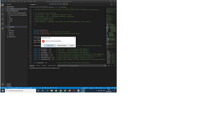
Aunque en las opciones he podido poner en alguna parte, que utilice las Librerías de Arduino, me ha tocado instalarlas de nuevo, y no encuentro la librería Easy Transfer.

Hay una opción, que es instalar una extensión, que es un paquete compatible con Arduino, entonces cuando le doy a Run > Start debugging, si hace algo, pero me sale este otro mensaje de error

Conflicted extensions with IntelliSense service were detected (Arduino). Code-completion, linting and navigation will not work properly. Please disable or uninstall them (Menu > View > Extensions).

Por lo tanto estoy en las mismas, no puedo comprobar el funcionamiento del programa, por lo menos con Atom, me confirmaba que los programas compilaban, con VSC, no puedo saber si compilan o no.

Although in the options I have been able to put somewhere, that I use the Arduino Libraries, I have had to install them again, and I can’t find the Easy Transfer library. .
There is an option, which is to install an extension, which is a package compatible with Arduino, then when I hit Run > Start debugging, if you do something, but I get this other error message

Conflicted extensions with IntelliSense service were detected (Arduino). Code-completion, linting and navigation will not work properly. Please disable or uninstall them (Menu > View > Extensions).

Therefore I am in them, I can not check the operation of the program, at least with Atom, confirmed to me that the programs compiled, with VSC, I can not know if they compile or not.

Buenas noches.

Ya puedo ver el funcionamiento del programa en VSC, pero me da el siguiente error de biblioteca.

Good night.

I can already see how the program works in VSC, but it gives me the following library error.

DEBUG: Current (simavr) On-board (simavr)
PACKAGES:
 - framework-arduino-avr 5.0.0
 - toolchain-atmelavr 1.50400.190710 (5.4.0)
LDF: Library Dependency Finder -> http://bit.ly/configure-pio-ldf
LDF Modes: Finder ~ chain, Compatibility ~ soft
Found 14 compatible libraries
Scanning dependencies...
No dependencies
Building in debug mode
Compiling .pio\build\megaatmega2560\src\main.cpp.o
Compiling .pio\build\megaatmega2560\FrameworkArduino\abi.cpp.o
src\main.cpp:154:54: fatal error: PS2X_lib.h: No such file or directory

******************************************************************
* Looking for PS2X_lib.h dependency? Check our library registry!
*
* CLI  > platformio lib search "header:PS2X_lib.h"
* Web  > https://platformio.org/lib/search?query=header:PS2X_lib.h
*
******************************************************************

compilation terminated.
*** [.pio\build\megaatmega2560\src\main.cpp.o] Error 1
===================================================== [FAILED] Took 6.84 seconds =====================================================
The terminal process terminated with exit code: 1

Terminal will be reused by tasks, press any key to close it.

The PS2X library is not yet registered with PlatformIO – I suggest you go to GitHub - simondlevy/PS2X_lib: Arduino Playstation2 library with compiler warnings fixed, download the ZIP file (https://github.com/simondlevy/PS2X_lib/archive/master.zip), then create a new folder in lib/ called PS2X_lib where you put in the files from the ZIP file so that the structure is …

lib/
   PS2X_lib/ 
      PS2X_lib.cpp
      PS2X_lib.h
      ...

then add the line

lib_deps = 
   PS2X_lib

into the platformio.ini so that the library is looked for by PlatformIO.

1 Like

The PlatformIO and Arduino extension are not compatible with each other – remove one of them.

1 Like

Same procedure as above – this is not registered in the PIO library registry (PlatformIO Registry) so you’d need to manually add it in the lib/ folder – downloads are available at the library’s github page which I linked above: GitHub - madsci1016/Arduino-EasyTransfer: An Easy way to Transfer data between Arduinos.

1 Like

Todas mis preguntas y problemas se han solucionado con estas 3 respuestas de Maxgerhardt, muchas gracias.

All my questions and problems have been solved with these 3 maxgerhardt answers, thank you very much.

Buenas noches.
Lo primero que yo tengo que hacer es darle a usted las gracias por su tiempo y sus comentarios, y por haberse leído las 50.000 líneas de mis explicaciones del proyecto y mis problemas.
Sus respuestas me están siendo de gran ayuda, muchas gracias, de verdad.
Ahora mis preguntas como puede ver, son mucho más cortas y concretas. Espero que no se canse de contestarme, realmente usted me está siendo de gran ayuda.

Un saludo, y muchas gracias

Good night.
The first thing I have to do is thank you for your time and feedback, and for reading the 50,000 lines of my explanations of the project and my problems.
Your answers are being of great help to me, thank you very much, really.
Now my questions as you can see, are much shorter and more concrete. I hope you don’t get tired of answering me, you’re really being very helpful to me.

Greetings, and thank you very much.

Creo que sería buena idea, decirles a los administradores, que deberían dejar subir los códigos como ficheros adjuntos comprimidos, para que se pudieran ver al otro lado de mi pantalla, y ustedes pudieran ver los errores de código como los veo yo.

I think it would be a good idea to tell the administrators, that they should let the codes go up as compressed attachments, so that they could be seen on the other side of my screen, and you could see the code errors as I see them.

Bueno, ahora que los programas ya no me dan errores de compilación, gracias a las respuestas de Maxgerhardt, debería de pasar al siguiente paso, que el VSC, me dijese de alguna manera, como se comporta el programa, que hay que mejorar, cuánto tiempo se tarda en ejecutar el programa, que instrucciones están retrasando la ejecución del programa, por que otras órdenes las debería de cambiar, etc.
No sé cómo explicarlo, que VSC, me diga algo mas a cerca de los códigos. Para que me diga VSC, algo más que el programa compila, que eso ya lo sabía antes con el IDE de Arduino.
Pero no veo que otros botones de opciones ni de ejecución hay, el botón más interesante que he visto es el de RUN, con el que se construye y se compila el programa, pero en mi caso, eso ya lo traía hecho desde el IDE de Arduino.
Un saludo.

Well, now that the programs no longer give me compilation errors, thanks to Maxgerhardt’s responses, I should move on to the next step, that the VSC, I would say somehow, how the program behaves, that it has to improve, how long it takes to run the program, that instructions are delaying the execution of the program, because other commands should change them Etc.
I don’t know how to explain it, that VSC, tell me something else about the codes. To tell me VSC, more than just the program compiles, that I already knew that before with the Arduino IDE.
But I do not see that other options or execution buttons there, the most interesting button I have seen is that of RUN, with which the program is built and compiled, but in my case, that already brought it done from the Arduino IDE.
Greetings.

I’m not quiet sure if I read this correctly, but there are a lot more features in PlatformIO than the “Build” and “Upload” button. See the documentation at Your Gateway to Embedded Software Development Excellence — PlatformIO latest documentation. A main feature is the easy project configuration with which one can create multiple environments for different target boards or source code files.

I know that in your particular case you’d like extended debugging on the AVR, but as said above that’s not there yet for the AVR. Although we might want to revisit VSCode PIO debugger for AVR which may be a working AVR debugger using a serial adapter…

Either directly copy-paste code in Markdown formatted text (Markdown Cheatsheet · adam-p/markdown-here Wiki · GitHub) or upload it on popular platforms such github.com as e.g. a gist (https://gist.github.com/) and post the link to, like e.g.

Anyways if there are code compilation problems or question on general programming or “why does this code fail” question, I can answer them.

1 Like

Buenas noches.

Muchísimas gracias por su tiempo y sus respuestas, quiero que sepa que le estoy muy agradecido, y me estoy tomando sus respuestas muy enserio, y me están ayudando mucho a resolver mis problemas de novato.

Si usted está leyendo bien, precisamente a eso me refiero, a hacer algo más que “Construir” y “Cargar” un programa.

Lo de subir los programas, entiendo que es falta de costumbre de utilizar el foro, y no saber cómo hacerlo, al no ver un botón para adjuntar los archivos del programa, digamos que ha sido un pensamiento en voz alta, porque entendía que tenía que haber una manera de hacerlo, y a demás tiene que ser fácil, pero yo no entendía ni encontraba cómo hacerlo.

Muchas gracias por los enlaces.

Todavía no estoy registrado en Github, porque entiendo que es una página lo bastante seria, como para publicar mis programas que no funcionan, y no estoy orgulloso de ellos para nada, y lo mas que puedo conseguir es que alguien los encuentre y me llame la atención, con razón, por publicar una cosa que no funciona.

Voy a leer los enlaces que me ha puesto, para comprobar si se puede hacer algo más con VSC y PIO, sobre la placa Arduino Mega 2560, pero por lo que usted me dice, intuyo que voy a poder hacer poco más de lo que ya he hecho, con su ayuda.

Ya hace unos días que compre unas placas ESP32, y están de camino, no deben de tardar en llegarme, supongo que con estas placas si voy a poder hacer más cosas con los programas, y luego, devolver los programas a Arduino, o quedarme con los ESP32, ya puestos me daría igual usar unas placas u otras en mi proyecto, lo que me interesa, es que los programas funcionen correctamente.

Adelantándome bastante a los acontecimientos, ya que no tengo todavía los ESP32, supongo que se podrán utilizar los programas con la estructura que tienen, aunque haya que hacer alguna VARIACIÓN MÍNIMA del programa y de los pines utilizados. Ya he leído en varios sitios, que hay algunos pines que no se pueden utilizar para conectar componentes externos, puesto que esos pines son utilizados para el propio sistema y funcionamiento del ESP32.

Me refiero a que haya un ESP32 dentro del vehículo, que controle los ESC o BEC de los motores, y que controle los sensores así como sus datos, y los envié a otro ESP32 que esté en el puesto de control, y mediante EasyTransfer, por un cable CAT6, y que reciba esos datos. Y que esos datos los pueda ver en una pantalla Nextion de 5 pulgadas. Que con el ESP32 de control, pueda manejar el mando de PS2, y el otro ESP32, reciba esos datos del mando y los interprete. Pudiendo aprovechar al máximo los programas que ya tengo hechos.

Entiendo que la mejor manera de aprovechar las placas ESP32 es con la comunicación wifi, pero mi proyecto tiene el problema añadido de que el ROV, cuando trabaja, está sumergido en el agua, por lo tanto la opción de usar la wifi, queda descartada, por eso es que utilizo EasyTransfer y el cable.

Muchas gracias de nuevo, por ofrecerme su ayuda en la programación, pero creo que ahora mismo podemos hacer poco más de lo que ya hemos hecho, sin las pacas ESP32.

No estoy rechazando su ayuda, ni mucho menos, pero en este momento, como comenta usted en su respuesta, no podemos hacer una depuración extendida de los códigos. De todas formas, voy a leer los enlaces, a ver si se pudiera hacer algo más.

Voy a subir los códigos, siguiendo sus instrucciones, para que los vea, por curiosidad, por si usted ve algo que le pueda resultar “incomodo de procesar” por cualquiera de las placas, y como entrenamiento de adjuntar los ficheros.

Le vuelvo a dar las gracias por su tiempo y sus comentarios, es un lujo poder contar con sus respuestas, está siendo un tutor magnifico, muchas gracias.

Y no se preocupe, que voy a seguir publicando cualquier mas mínima duda que tenga.

Un saludo.

Good night.

Thank you very much for your time and your answers, I want you to know that I am very grateful to you, and I am taking your answers very seriously, and are helping me a lot to solve my rookie problems.

If you are reading well, that’s exactly what I mean, to do more than “Build” and “Load” a program.

I understand that it is unusual to use the forum, and not knowing how to do it, by not seeing a button to attach the program files, let’s say it was a thought out loud, because I understood that there had to be a way to do it, and others it has to be easy, but I did not understand or find how to do it.

Thank you very much for the links.

I’m not registered on Github yet, because I understand that it’s a serious enough page, to publish my programs that don’t work, and I’m not proud of them at all, and the most I can get is for someone to find them and get my attention, rightly, for posting a thing that doesn’t work.

I will read the links you have put me, to check if you can do something else with VSC and PIO, on the Arduino Mega 2560 board, but from what you tell me, I intuit that I will be able to do little more than I have already done, with your help.

Already a few days ago I bought some ESP32 plates, and they are on their way, they should not take long to arrive, I suppose with these plates if I will be able to do more things with the programs, and then, return the programs to Arduino, or stay with the ESP32, already put I would not mind using some plates or others in my project, which I am interested in , is that the programs work properly.

Getting in the way of the events, since I don’t have the ESP32 yet, I suppose you will be able to use the programs with the structure that they have, even if you have to do some MINIMUM VARIATION of the program and the pins used. I have already read in several sites, that there are some pins that cannot be used to connect external components, since those pins are used for the system itself and operation of the ESP32.

I mean that there is an ESP32 inside the vehicle, that controls the ESC or BECs of the engines, and that controls the sensors as well as their data, and I sent them to another ESP32 that is at the checkpoint, and via EasyTransfer, by a CAT6 cable, and that receives that data. And let that data be seen on a 5-inch Nextion screen. That with the ESP32 control, you can operate the PS2 command, and the other ESP32, receive that data from the controller and interpret it. Being able to make the most of the programs that I already have made.

I understand that the best way to take advantage of ESP32 boards is with wifi communication, but my project has the added problem that the ROV, when working, is submerged in water, therefore the option to use the wifi, is discarded, that is why I use EasyTransfer and the cable.

Thank you very much again, for offering me your help in programming, but I think right now we can do little more than we have already done, without the ESP32 bales.

I’m not refusing your help, much less, but at this time, as you say in your response, we can’t do an extended debugging of the codes. Anyway, I’m going to read the links, see if anything else could be done.

I will upload the codes, following your instructions, so that you see them, out of curiosity, in case you see anything that you may find “uncomfortable to process” by any of the plates, and as a training to attach the files.

I thank you again for your time and your comments, it is a luxury to have your answers, you are being a magnificent tutor, thank you very much.

And don’t worry, I’m going to keep posting any more doubts I have.

Greetings.

Bueno, pues ya me he registrado en Github, más que nada, porque como los programas tienen tantas líneas de código, no los puedo publicar como texto en el foro de Platform IO.

Los he llamado “Programas ROV en evolución”, y en el nombre de cada programa, he puesto la advertencia “no funcionan aun”, para que nadie que pueda verlos se confunda con programas listos para utilizar, cuando estén terminados, editare los títulos y los cambiare por “ya funcionan”, u otra cosa que se me ocurra cuando llegue el momento.

Este es el enlace a los programas.

Un saludo.

Well, I’ve already registered on Github, mostly, because since programs have so many lines of code, I can’t post them as text on the Platform IO forum.

I’ve called them “EVOLVING ROV Programs,” and in the name of each program, I’ve put the “not work yet” warning, so that no one who can see them is mistaken for ready-to-use programs, when they’re finished, edit the titles and change them to “they already work”, or something else I can think of when the time comes.

This is the link to the programs.

Greetings.

Maxgerhardt, quiero pedirte un favor.

Quieres abrir el enlace de Github, y mirar si puedes trabajar con él, me refiero a descargar los programas y las librerías, y comprobar que lo puedes pasar al programa con el que tu trabajes, quiero comprobar que lo he hecho bien.

Muchas gracias, un saludo

Maxgerhardt, I want to ask you a favor.

You want to open the Github link, and see if you can work with it, I mean download the programs and libraries, and check that you can pass it to the program you work with, I want to check that I have done well.

Thank you very much, a greeting

Buenos días.
Maxgerhardt, ya he leído los enlaces sobre la depuración extendida

Pero lamento comentarle que son demasiado complicados para mi, y se escapan a mis conocimientos, por lo tanto me toca esperar a que me lleguen las placas ESP32.

Muchas gracias, un saludo.

Good morning.
Maxgerhardt, I’ve already read the links about extended debugging

But I regret to tell you that they are too complicated for me, and they are beyond my knowledge, so it is my turn to wait for the ESP32 plates to arrive.

Thank you very much, a greeting.