Teensy 4.1 Uploading with JLink

Do the things listed above make a difference?

Also, if you add

debug_tool = custom
debug_server = 
   C:\Users\<user>\.platformio\packages\tool-jlink\JLinkGDBServerCL.exe 
   -singlerun 
   -if 
   jtag 
   -select 
   USB 
   -device 
   MIMXRT1062xxxxA 
   -port 
   2331
debug_port = localhost:2331
debug_init_cmds =
   target extended-remote $DEBUG_PORT
   monitor clrbp
   monitor speed auto
   monitor reset
   monitor halt
   $LOAD_CMDS
   $INIT_BREAK

(with adapted path info) to the platformio.ini, does debugging work in VSCode?

I have restarted VS code, updated platformio, reinstalled platformio, created a new project which is spaces free. None of these made a difference yet, but I have yet to uninstall virus protection/disable defender.

The custom debug tools almost work. It was able to flash the teensy once but then VS Code jumped to a random arduino lib and the arduino became unstable to where I couldn’t do anything and had to reflash it with JFlash. Not sure if that is a different issue or what.

I appreciate all the help… I’m still trying everything I can.

Well the base error is that PlatformIO doesn’t seem to be able to execute any commands from inside VSCode to the Jlink tools.

When I do “Start Debugging” in VSCode with the above platformio.ini, I do get the JLink output, telling me it failed to start (since no JLink is connected of course)

And I do get the “Verbose Upload” JLink output as indicated above.

I’m not excluding antivirus to be a culprit if you get no output at all.

It seems to help in your setup though to specify explicit commands.

For uploading you can also try the platformio.ini

[env:teensy41]
platform = teensy
board = teensy41
framework = arduino
upload_protocol = custom
upload_command =
   $PROJECT_PACKAGES_DIR/tool-jlink/JLink.exe 
   -device 
   MIMXRT1062xxxxA
   -if 
   jtag
   -autoconnect 
   1
   -NoGui 
   1
   -CommanderScript 
   upload.jlink

And a upload.jlink file at the same level as the platformio.ini with content

h
loadfile .pio\build\teensy41\firmware.hex
r
q

Then check “Verbose Upload” if the tool is invoked correctly and flashes correctly (docs).

I went ahead and uninstalled my antivirus and disabled defender temporarily but unfortunately it is still hanging up on upload.

I also tried the above, here is the end of the output… still looks to be the same issue

arm-none-eabi-objcopy -O ihex -R .eeprom .pio\build\teensy41\firmware.elf .pio\build\teensy41\firmware.hex
MethodWrapper([“checkprogsize”], [“.pio\build\teensy41\firmware.elf”])
Advanced Memory Usage is available via “PlatformIO Home > Project Inspect”
RAM: [= ] 7.9% (used 41660 bytes from 524288 bytes)
Flash: [ ] 0.2% (used 14304 bytes from 8126464 bytes)
.pio\build\teensy41\firmware.elf :

section size addr

.text.progmem 6928 1610612736

.text.itcm 6320 0

.fini 4 6320

.text.itcm.padding 26444 6324

.data 1056 536870912

.bss 7840 536871968

.bss.dma 12384 538968064

.debug_frame 96 0

.ARM.attributes 46 0

.comment 110 0

Total 61228
([“upload”], [“.pio\build\teensy41\firmware.hex”])
AVAILABLE: custom, jlink, teensy-gui
CURRENT: upload_protocol = custom
C:\Users<user>.platformio\packages\tool-jlink\JLink.exe

Please file a bug in Issues · platformio/platform-teensy · GitHub with reference to this thread, I have no idea why this hangs up. The standard platformio.ini from the first post should work.

As an extravangza test one could install VirtualBox + Ubuntu 20 + Guest extensions and test whether it works in that virtual machine, when the USB device is forwarded. But as said, the invocations work for me on my Windows 10 x64 system without problems.

Correction to previous platformio.ini: It should have been

[env:teensy41]
platform = teensy
board = teensy41
framework = arduino
upload_protocol = custom
upload_flags =
   -device 
   MIMXRT1062xxxxA
   -if 
   jtag
   -autoconnect 
   1
   -NoGui 
   1
   -CommanderScript 
   upload.jlink
upload_command = $PROJECT_PACKAGES_DIR/tool-jlink/JLink.exe $UPLOAD_FLAGS

But that doesn’t change a lot regarding the initial problem.

1 Like

I have managed to get it working. I added/removed a few things to my ini after @maxgerhardt 's suggestions.
Here is my platformio.ini:

[env:teensy41]
platform = teensy
board = teensy41
framework = arduino
upload_protocol = custom
upload_flags =
   -device
   MIMXRT1062xxx6A
   -speed
   4000
   -if
   jtag
   -jtagconf
   -1,-1
   -autoconnect
   1
   -NoGui
   1
   -CommanderScript
   "upload.jlink"
upload_command = $PROJECT_PACKAGES_DIR\tool-jlink\JLink.exe $UPLOAD_FLAGS
debug_tool = custom
debug_server = 
   C:\Users\\\<user>\\.platformio\packages\tool-jlink\JLinkGDBServerCL.exe 
   -singlerun 
   -if 
   jtag 
   -select 
   USB 
   -device 
   MIMXRT1062xxx6A 
   -port 
   2331
   -speed
   4000
debug_port = localhost:2331
debug_init_cmds =
   target extended-remote $DEBUG_PORT

with an upload.jlink file at the root of the project:

r
loadfile .pio\build\teensy41\firmware.hex
r
q

Thanks for helping @maxgerhardt
I’m still not sure what the underlying issue is, I doubt I will look into it much further but if a dev is interested I can work with them to figure it out.

2 Likes

How hard was the mod need to get this working, do you have pictures? I’ve put this off as I did not find any great guides as to the how to do it! hint hint :slight_smile:

I have not seen anyone else do it with a Teensy 4/4.1 yet. The Teensy 3s are a bit easier to mod since they had debug pads on the board, but you still needed to remove the same chip. It requires good soldering skills, hot air station, microscope, magnet wire, etc. I am still in the early stages of the modification so it is a mess. I am waiting on a pcb to be made which should make this presentable.
Here are some pics.


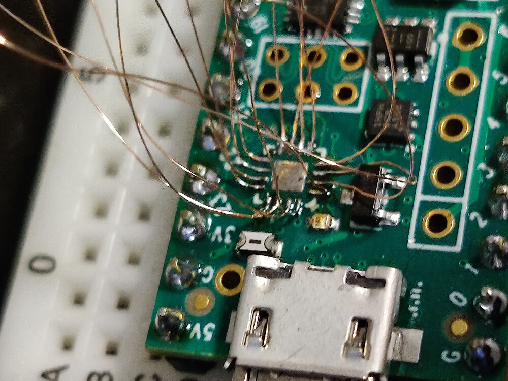
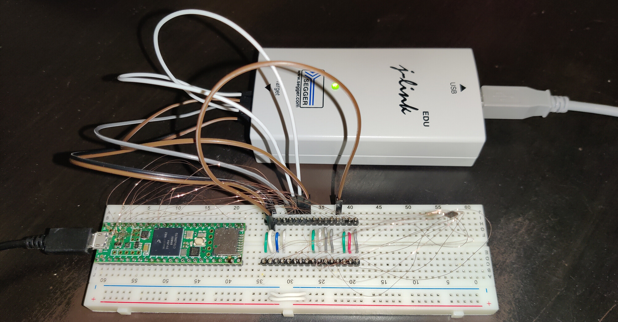
The mod requires removing the MKL02Z32VFG4 to access the JTAG pads, connecting those to a J-Link, and reconnecting the chip to the other (non JTAG) pads to keep everything happy… And yes… that is the MKL02Z32VFG4 floating off to the right.

@datkins47 Let me know if you need guidance, if you decide to take it on.

1 Like

credit due there, just wow! might wait before tackling that, love the teensy 4.1 with ethernet but not sure that’s ready for my solder blobbing skills, you thinking pcb to replace chip?

1 Like

I designed a flex pcb that will be soldered in place of the chip and extrude out the right side of the board and breakout the pins so they can be jumpered over to the J-Link. It will involve de soldering the M0 chip, soldering the m0 to the flex pcb, and soldering the flex pcb back in place of the M0 on the Teensy. Then you have normal 2.54mm headers to jumper from.

I left the chip in the equation because it is handling a few things besides just programming, without it I believe the processor never starts up a DCDC converter. Also this way you can jumper the pins back to the chip and use it as normal.

might be interested in that if you get going, that’s soldering we can do!

A little update for anyone who comes across this. I was getting this error during upload

****** Error: Failed to prepare for programming.
RAM check failed @ addr 0x20001D8C.
RAM check failed while testing 0x7FF0 bytes @ addr 0x20001D8C.
Error while determining flash info (Bank @ 0x60000000)
Unspecified error -1

I found a suggestion to reset and halt before uploading and that seems to have fixed this issue. The new upload.jlink file is as follows:

r
loadfile .pio\build\teensy41\firmware.hex
r
q

I will also update the solution post to reflect this.

Thanks for that great guide and all the information regarding the debugging.
I was able to set my teensy 4.1 up for the JLink connection.
With the platform.ini above, I was able to upload via JTAG and start the debugger, but the debugger kept jumping through the code in (at least for me) uncomprehensive steps.
As far as I understand, this is probably to some compiler optimization that does not work with the debugger. As this may be relevant to someone else trying this, here’s the platformio.ini that worked for me:

[env:teensy41]
platform = teensy
board = teensy41
framework = arduino
lib_extra_dirs = ~/Documents/Arduino/libraries
upload_protocol = custom
upload_flags =
   -device
   MIMXRT1062xxx6A
   -speed
   4000
   -if
   jtag
   -jtagconf
   -1,-1
   -autoconnect
   1
   -NoGui
   1
   -CommanderScript
   "upload.jlink"
upload_command = $PROJECT_PACKAGES_DIR\tool-jlink\JLink.exe $UPLOAD_FLAGS
;debug_tool = custom
debug_tool = jlink
debug_server = 
   ${platformio.packages_dir}\tool-jlink\JLinkGDBServerCL.exe ; edited as suggested by Ivan
   -singlerun
   -if 
   jtag 
   -select 
   USB 
   -device 
   MIMXRT1062xxx6A 
   -port 
   2331
   -speed
   4000
debug_port = localhost:2331

I changed the debug_protocol back to jlink, but overrode some of its parameters, which I guess left the rest of the compiler’s parameters untouched. Adding debug_build_flags = -O0 -ggdb3 -g3 did not work for me, but this did.
I used the upload.jlink file described here.

Thanks again for this thread, really glad I found it, if I had been successful at all, it would have taken a lot longer without it!

Cheers
Philipp

A few hints for you that might help you to solve this issue:

  1. Make your config portable using Interpolation of Values. Replace hardcoded $PROJECT_PACKAGES_DIR and C:\Users\\\rovedo\\.platformio\packages values by ${platformio.packages_dir}/tool-jlink/JLink.exe
  2. Change Buid Configuration to the debug mode.
  3. Build project in verbose mode pio run -v.

So, you will see all flags. I can suppose you will need to remove some default flags using the build_unflags option.

In any case, please share your progress here. Thanks in advance!

Hi Ivan,

thanks a lot for your reply, I edited the script to incorporate your suggestion.

I think I didn’t make myself very clear reading over my text again:

The configuation I posted, which is slightly different to the one sp33 posted a while ago,
works perfectly for me (on multiple machines as well). Compiling, uploading and debugging are all running as expected.

I just wanted to post the ini in case someone else was struggling with debugging using the file originally suggested.

I am keen to give this a try, and have smd flex pcb tooling and experience. If it works I’d be happy to fab extras for the community. Might you be willing to share the schematic and layout or other advice? thanks very much!

I am willing to share what I have, it’s just not organized at the moment. Since posting this I have made multiple versions trying to come up with the best solution possible. Here are some pics of my progress.


Here is a sheet I was making to map out the pins, there’s a tab for links I referenced and pics of progress too.
https://docs.google.com/spreadsheets/d/1IHnKprGMN98fk_qJn_A1hpxdfL1dd9GDggG42iSkLR4/edit?usp=sharing

Main issues I had were pads lifting when trying to accomplish a through hole style soldering method. Once I Switched to using hot air without through holes, lining it up was the hardest part. Let me know which one you are interested in trying out, I have some KiCad files they just are not versioned very well unfortunately.

Hi @sp33 , I’m very interested in what you might be able to share. Really… no matter the condition. I have a huge need to use debug facilities of the chip. I am willing to pay for that capability too. Any help you could provide please let us know.

Note that there’s also a chip that is “close” to the Teensy (NXP iMX.RT1062) and has an evaluation kit for $110: MIMXRT1060-EVKB. Not sure if you can just flash a Teensy + Arduino firmware on it without modifications, but they should be relatively close so that adaptation is minimal and you have can have a debugger on that thing.