STM32-E407 doesn’t work on PIO

I am trying to make a “Hello World” example for the STM32-E407 board on PlatformIO with the Arduino framework but it doesn’t work.

I am able to upload the project, but the LED never blinks.

I followed the instruction in the user manual to set the jumpers and everything I have made is detailed on this page: GitHub - NicHub/STM32-E407-BLINK: Hello World example for the STM32-E407 board on PlatformIO with the Arduino framework..

Can someone help me to make this simple project work?

Note that I also asked Olimex about this issue, but without success for now.

Do you get output in the serial monitor? It is supposed to be something like:

START
HIGH
LOW
HIGH
LOW

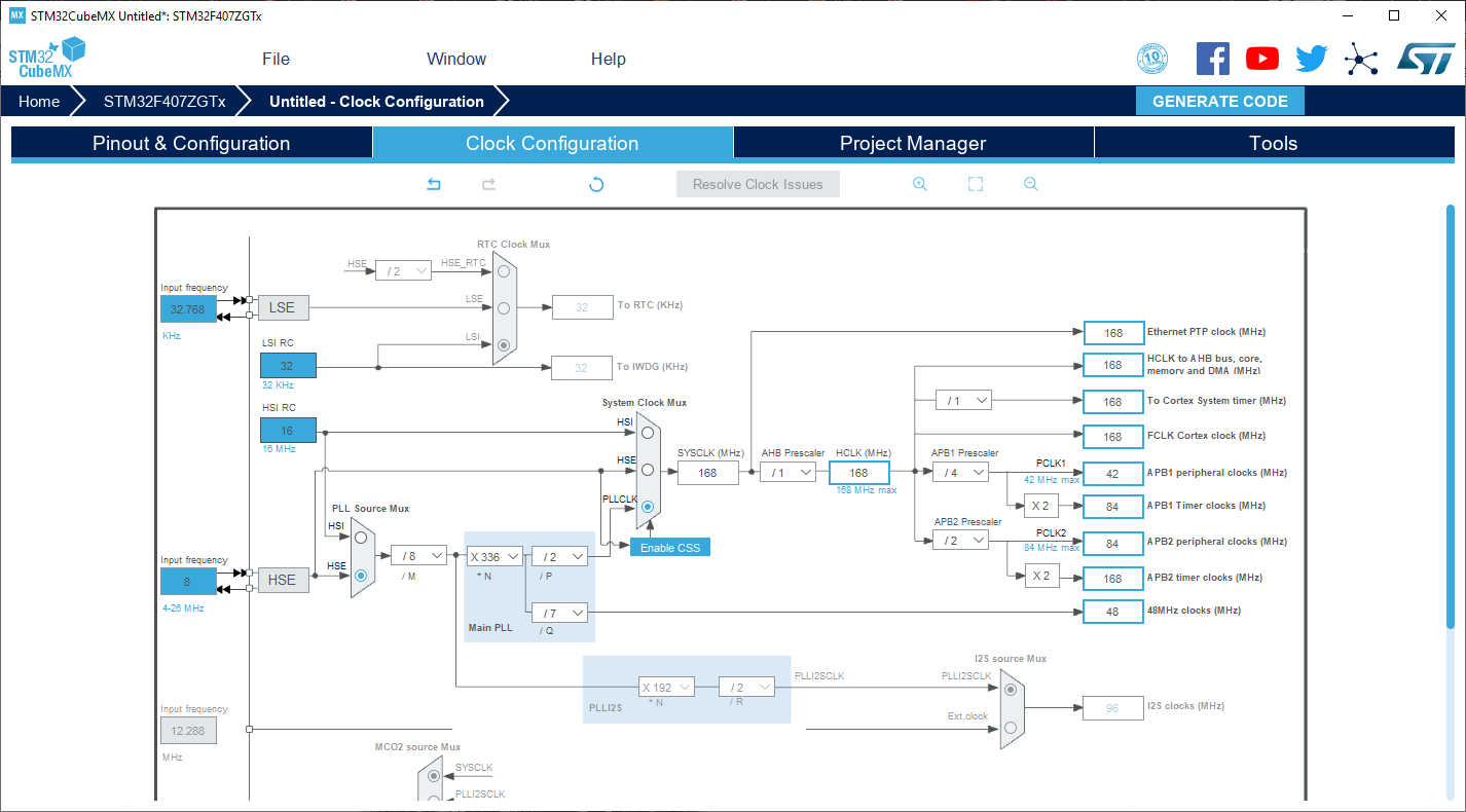
The black_f407zg is not the proper target / variant for it. The original board has an 8Mhz crystal for HSE on it. The arduino code (variant.cpp) in C:\Users\<home>\.platformio\packages\framework-arduinoststm32\variants\BLACK_F407XX\variant.cpp has code which initializes the PLL parameters (multipliers and divisors M,N,P,Q) as follows

WEAK void SystemClock_Config(void)
{

  RCC_OscInitTypeDef RCC_OscInitStruct;
  RCC_ClkInitTypeDef RCC_ClkInitStruct;

  /**Configure the main internal regulator output voltage
  */
  __HAL_RCC_PWR_CLK_ENABLE();

  __HAL_PWR_VOLTAGESCALING_CONFIG(PWR_REGULATOR_VOLTAGE_SCALE1);

  /**Initializes the CPU, AHB and APB busses clocks
  */
  RCC_OscInitStruct.OscillatorType = RCC_OSCILLATORTYPE_HSE;
  RCC_OscInitStruct.HSEState = RCC_HSE_ON;
  RCC_OscInitStruct.PLL.PLLState = RCC_PLL_ON;
  RCC_OscInitStruct.PLL.PLLSource = RCC_PLLSOURCE_HSE;
  RCC_OscInitStruct.PLL.PLLM = 8;
  RCC_OscInitStruct.PLL.PLLN = 336;
  RCC_OscInitStruct.PLL.PLLP = RCC_PLLP_DIV2;
  RCC_OscInitStruct.PLL.PLLQ = 7;
  if (HAL_RCC_OscConfig(&RCC_OscInitStruct) != HAL_OK) {
    _Error_Handler(__FILE__, __LINE__);
  }

  /**Initializes the CPU, AHB and APB busses clocks
  */
  RCC_ClkInitStruct.ClockType = RCC_CLOCKTYPE_HCLK | RCC_CLOCKTYPE_SYSCLK
                                | RCC_CLOCKTYPE_PCLK1 | RCC_CLOCKTYPE_PCLK2;
  RCC_ClkInitStruct.SYSCLKSource = RCC_SYSCLKSOURCE_PLLCLK;
  RCC_ClkInitStruct.AHBCLKDivider = RCC_SYSCLK_DIV1;
  RCC_ClkInitStruct.APB1CLKDivider = RCC_HCLK_DIV4;
  RCC_ClkInitStruct.APB2CLKDivider = RCC_HCLK_DIV2;

  if (HAL_RCC_ClockConfig(&RCC_ClkInitStruct, FLASH_LATENCY_5) != HAL_OK) {
    _Error_Handler(__FILE__, __LINE__);
  }
}

Which matches the parameters to get a full 168MHz SYSCLK for the Cortex-M4F core and the peripherals.

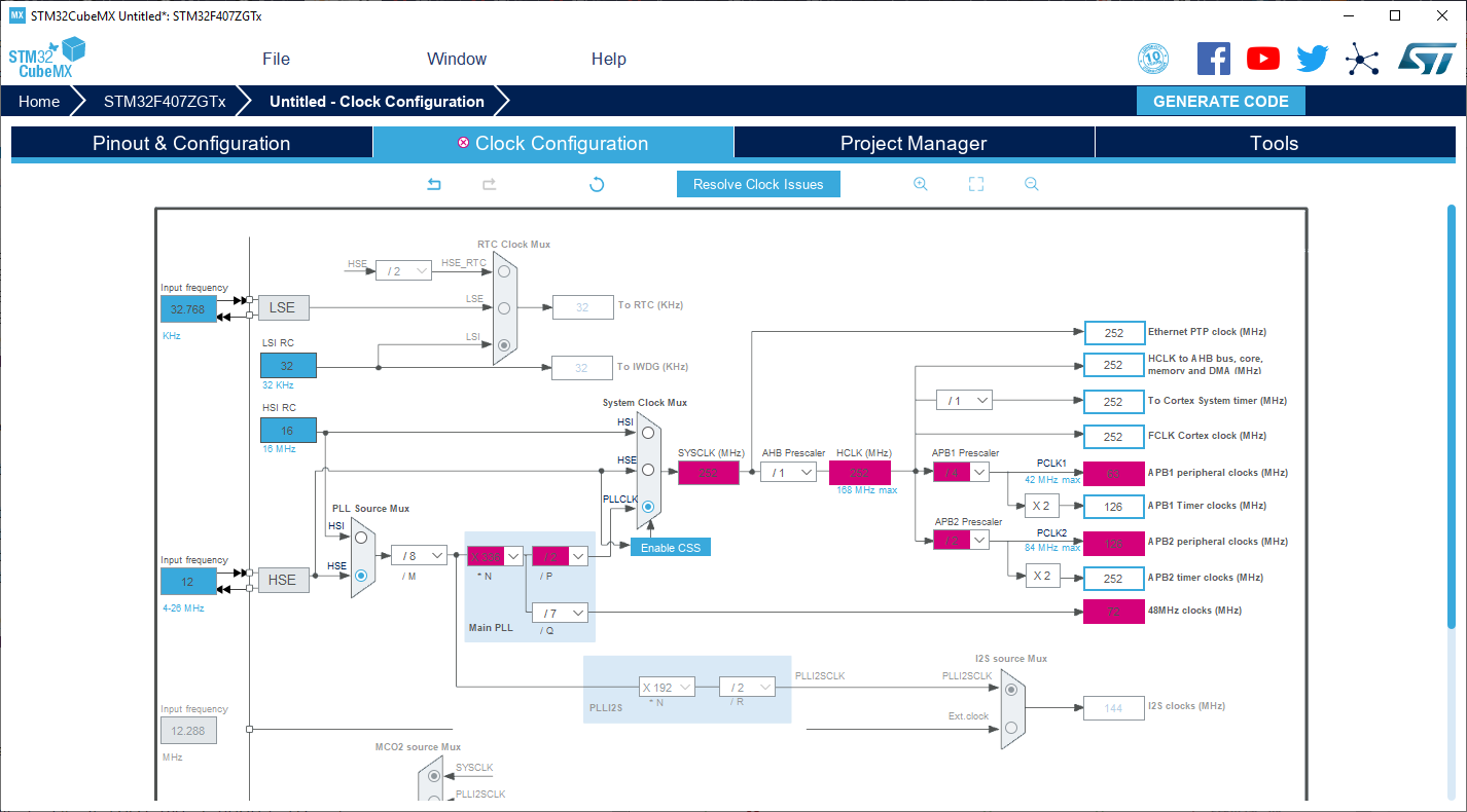
Your Olimex board however however has a 12MHz crystal (see schematics page 27)

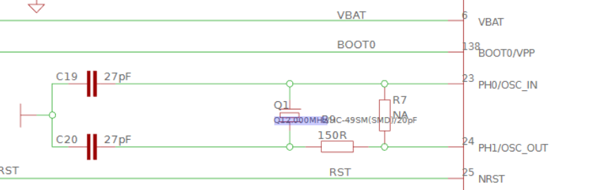
Without altering the PLL parameters we now get a higher-than-allowed HCLK.

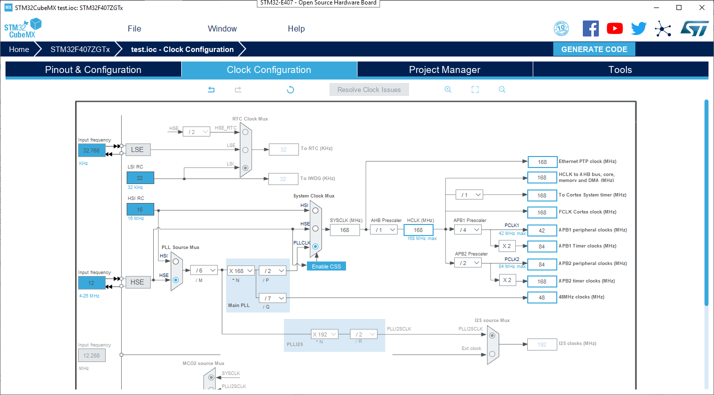
So you are operating your microcontroller out-of-specs and that won’t even boot. The following PLL initialization code is needed:

void SystemClock_Config(void)
{
  RCC_OscInitTypeDef RCC_OscInitStruct = {0};
  RCC_ClkInitTypeDef RCC_ClkInitStruct = {0};

  /** Configure the main internal regulator output voltage 
  */
  __HAL_RCC_PWR_CLK_ENABLE();
  __HAL_PWR_VOLTAGESCALING_CONFIG(PWR_REGULATOR_VOLTAGE_SCALE1);
  /** Initializes the CPU, AHB and APB busses clocks 
  */
  RCC_OscInitStruct.OscillatorType = RCC_OSCILLATORTYPE_HSE;
  RCC_OscInitStruct.HSEState = RCC_HSE_ON;
  RCC_OscInitStruct.PLL.PLLState = RCC_PLL_ON;
  RCC_OscInitStruct.PLL.PLLSource = RCC_PLLSOURCE_HSE;
  RCC_OscInitStruct.PLL.PLLM = 6;
  RCC_OscInitStruct.PLL.PLLN = 168;
  RCC_OscInitStruct.PLL.PLLP = RCC_PLLP_DIV2;
  RCC_OscInitStruct.PLL.PLLQ = 7;
  if (HAL_RCC_OscConfig(&RCC_OscInitStruct) != HAL_OK)
  {
    _Error_Handler(__FILE__, __LINE__);
  }
  /** Initializes the CPU, AHB and APB busses clocks 
  */
  RCC_ClkInitStruct.ClockType = RCC_CLOCKTYPE_HCLK|RCC_CLOCKTYPE_SYSCLK
                              |RCC_CLOCKTYPE_PCLK1|RCC_CLOCKTYPE_PCLK2;
  RCC_ClkInitStruct.SYSCLKSource = RCC_SYSCLKSOURCE_PLLCLK;
  RCC_ClkInitStruct.AHBCLKDivider = RCC_SYSCLK_DIV1;
  RCC_ClkInitStruct.APB1CLKDivider = RCC_HCLK_DIV4;
  RCC_ClkInitStruct.APB2CLKDivider = RCC_HCLK_DIV2;

  if (HAL_RCC_ClockConfig(&RCC_ClkInitStruct, FLASH_LATENCY_5) != HAL_OK)
  {
    _Error_Handler(__FILE__, __LINE__);
  }
}

Which brings your MCU to top-speed with valid params on a 12MHz crystal.

So you should test this by doing this local modification to your variant.cpp in the path I have noted above.

I further found it strange that Platformio’s board JSON file references the wrong linker file

However, the BLACK_F407XX folder does contain a ldscript.ld which is valid for this microcontroller and it should be used. Double check that in the compile commands (pio run -v).

Hi maxgerhardt,

Many thanks for your very detailed answer.

I changed the function SystemClock_Config in ~/.platformio/packages/framework-arduinoststm32/variants/BLACK_F407XX/variant.cpp (I am on macOS), but it doesn’t work.

Maybe it is because of the wrong Platformio’s board JSON file.

Do you have any other suggestions?

No, nothing is printed in the serial monitor.

Hm, clock speed definitely should have been at least one issue here. Can just try this code for SystemClock_Config()? (It uses HSI so no external crystal is needed.)

void SystemClock_Config(void)
{
  RCC_OscInitTypeDef RCC_OscInitStruct = {0};
  RCC_ClkInitTypeDef RCC_ClkInitStruct = {0};

  /** Configure the main internal regulator output voltage 
  */
  __HAL_RCC_PWR_CLK_ENABLE();
  __HAL_PWR_VOLTAGESCALING_CONFIG(PWR_REGULATOR_VOLTAGE_SCALE1);
  /** Initializes the CPU, AHB and APB busses clocks 
  */
  RCC_OscInitStruct.OscillatorType = RCC_OSCILLATORTYPE_HSI;
  RCC_OscInitStruct.HSIState = RCC_HSI_ON;
  RCC_OscInitStruct.HSICalibrationValue = RCC_HSICALIBRATION_DEFAULT;
  RCC_OscInitStruct.PLL.PLLState = RCC_PLL_ON;
  RCC_OscInitStruct.PLL.PLLSource = RCC_PLLSOURCE_HSI;
  RCC_OscInitStruct.PLL.PLLM = 8;
  RCC_OscInitStruct.PLL.PLLN = 168;
  RCC_OscInitStruct.PLL.PLLP = RCC_PLLP_DIV2;
  RCC_OscInitStruct.PLL.PLLQ = 7;
  if (HAL_RCC_OscConfig(&RCC_OscInitStruct) != HAL_OK)
  {
    _Error_Handler(__FILE__, __LINE__);
  }
  /** Initializes the CPU, AHB and APB busses clocks 
  */
  RCC_ClkInitStruct.ClockType = RCC_CLOCKTYPE_HCLK|RCC_CLOCKTYPE_SYSCLK
                              |RCC_CLOCKTYPE_PCLK1|RCC_CLOCKTYPE_PCLK2;
  RCC_ClkInitStruct.SYSCLKSource = RCC_SYSCLKSOURCE_PLLCLK;
  RCC_ClkInitStruct.AHBCLKDivider = RCC_SYSCLK_DIV1;
  RCC_ClkInitStruct.APB1CLKDivider = RCC_HCLK_DIV4;
  RCC_ClkInitStruct.APB2CLKDivider = RCC_HCLK_DIV2;

  if (HAL_RCC_ClockConfig(&RCC_ClkInitStruct, FLASH_LATENCY_5) != HAL_OK)
  {
    _Error_Handler(__FILE__, __LINE__);
  }
}

Also, do you have access to an ST-Link debug probe (or really any ARM SWD debugger) so you could step through the code and see where it hangs?

And could you also tell me whether GitHub - maxgerhardt/STM32-E407-BLINK: Hello World example for the STM32-E407 board on PlatformIO with the STM32Cube framework. toggles the LEDs successfully (uses STM32Cube)

I tried your new SystemClock_Config and it doesn’t work.
I bought a ARM-USB-OCD-H debugger which should be delivered tomorrow.

I tried your STM32Cube version of STM32-E407-BLINK and it works.
The board LED (PC13) and the Arduino LED (PA5) are blinking one after the other at ~2 Hz.

Very interesting, because the STM32Cube version I posted uses that exact SystemClock_Config() as you can see. But the timing is still off, shouldn’t be 2Hz but 5Hz…

Can you change this to do delay 1000

And then comment out

Is the timing correct now at 1Hz? And the behaviour is different once the previous two lines are commented back in?

I was wrong, the timing is 5 Hz and not 2 Hz. And if I change the delay to 1000, the frequency is then 1 Hz which is correct.

Commenting out SystemClock_Config(); and SystemCoreClockUpdate(); didn’t change anything.

So now I am able to program my E407 board with the STM32Cube framework, thank you.

As this framework is brand new to me, may I ask you how I can do PWM on pin A5 ? I tried to find my way on Google, but most of the examples are for Keil… The idea is to drive a servo motor.

Hi @ouilogique! Could you please try to update the platform to v5.6.0 and run your Arduino example again? We’ve added a workaround for boards with core coupled memory so BLACK_F407XX variant should work now. Thanks!

1 Like

This is good, it suggests that HSI works without problems. However this means that the reason the Arduino framework is not working is only partly becaue of wrong clock and there is something else. Out of curiosity, what if you replace SystemClock_Config() again with the HSE startup routine from the beginning of the thread in the STM32Cube example?

PWM with STM32HAL functions are kind of complicated, requiring the setup of a hardware timer and other stuff. There is an explanation here.

valoros’s answer suggest that it might work now for Arduino after a platform update (either in the vscode update GUI or pio platform update). If not, you need breakpoints at strategic breakpoints during the bootup to see where it goes wrong. Like <user>\.platformio\packages\framework-arduinoststm32\system\STM32F4xx\system_stm32f4xx.c SystemInit(),SystemCoreClockUpdate() or SystemClock_Config() from the variant folder, main() function etc. Also, this define might help?

Hi @valeros. What platform are you talking about? PlatformIO version is “Home 2.3.2·Core 4.0.2”. So I guess you are talking about another platform…

You can update your platform here PlatformIO Home -> Platforms -> Updates -> ST STM32 -> Update to 5.6.0

After upgrading the STM32 platform to version 5.6.0, the LEDs are blinking but the serial communication does not seem to work. I connected an UART dongle to the TX and GND pins of the UEXT connector and also on the same pins of the BOOT headers, but there are no messages.

Great that this is working now. For UART the pins of the Serial object is (from variant.h)

#define SERIAL_UART_INSTANCE    1 //ex: 2 for Serial2 (USART2)
#define PIN_SERIAL_RX           PA10
#define PIN_SERIAL_TX           PA9

The UEXT connector has PC6 (TX) and PC7 (RX) which belong to USART6. PA9 in the board is unfortunately also OTG_FS_VBUS so its shorted to the VBUS connection of the USB_OTG1 connector. (see above schematics page 27). I’d say it’s the easiest to just enable the serial object for USART6 and use it. (Or, actually create a proper variant for the board in the arduino framework…)

Example main.cpp

#include <Arduino.h>

#define LED_STME407 PC13
#define LED_ARDUINO PA5

/**
 *
 */
void setup()
{
    pinMode(LED_STME407, OUTPUT);
    pinMode(LED_ARDUINO, OUTPUT);

    Serial6.begin(115200);
    Serial6.println("\nSTART");
}

/**
 *
 */
void loop()
{
    Serial6.println("HIGH");
    digitalWrite(LED_STME407, HIGH);
    digitalWrite(LED_ARDUINO, HIGH);
    delay(200);

    Serial6.println("LOW");
    digitalWrite(LED_STME407, LOW);
    digitalWrite(LED_ARDUINO, LOW);
    delay(200);
}

Needs platformio.ini

[platformio]
default_envs = black_f407zg

[env]
monitor_speed = 115200
build_flags =
    -D BAUD_RATE=${env.monitor_speed}
    -D HSE_VALUE=12000000
    -D PIO_FRAMEWORK_ARDUINO_SERIAL_WITHOUT_GENERIC
    -D ENABLE_HWSERIAL6


[env:black_f407zg]
platform = ststm32
board = black_f407zg
framework = arduino
upload_protocol = dfu
build_flags = ${env.build_flags}
1 Like

Yes! Now my Hello World example works completely! Many thanks to you maxgerhardt and valeros!

I have updated my git depot of this project to reflect what was said in this thread. Unfortunately, my posts with links are labeled “This post was flagged by the community and is temporarily hidden.” Is it possible for you to unflag my first post or to post the URL to my git depot so that people interested in this topic can see the link?

One last question: I can read the serial output on the UEXT connector and on the BOOT header (beside the UEXT connector). Is it possible to read the serial output on USB-OTG 1 or 2?

1 Like

Great news! :slight_smile:

If you haven’t done it already, another improvement would be to move the SystemClock_Config() from the framework-arduinostm32 folder (which might be overwritten by updates) into the actual main firmware. This should work because the function is marked _WEAK in the framework, meaning it should be possible to be overwritten by simply pasting the correct SystemClock_Config() in the main.cpp but adding extern "C" in front of the void .. (to get C name linkage because the original function was defined in a .c file, not .cpp file). Worth a try.

A wrongly approved spam flag for Olimex links has been reverted now.

You mean you want the device to be a USB CDC (aka virtual COM port) by using its USB peripheral? Yeah Arduino STM32 has SerialUSB support, needs to be activated via some build flags.

Take a look at Difficulty with getting USB serial [USB CDC] working - #6 by maxgerhardt and try to incorporate the build flags with the current ones. Important: You probably need to remove PIO_FRAMEWORK_ARDUINO_SERIAL_WITHOUT_GENERIC and also need a working SystemClock_Config() from HSE! The internal HSI will not work for USB because it is too inaccurate, this needs the HSE. (see Solved: STM32CubeMX 4.15.1 - cannot select HSI as PLL sour... - STMicroelectronics Community). I don’t know which connector it will choose though without further looking into it.

Yes, it is great that it works. At the beginning my idea was only to test the board quickly. I thought the Arduino framework would help to go fast, but I was wrong. I need to learn STM32Cube for my job, but the learning curve is quite steep so I decided to test the board with the Arduino framework first…

For the SystemClock_Config(), I can do as you said, but I really wonder if this is necessary as it works with the original variant.cpp file. I tried it on a fresh install of PlatformIO and it works. Moreover you say that for USB CDC to work, HSE is needed and it is the case in the original variant.cpp file.

I tried to activate USB CDC on my board, but it doesn’t work. The compilation and upload work OK, but no new serial interface is shown on my computer. Here is my platformio.ini:

[platformio]
default_envs = black_f407zg


[env]
monitor_speed = 115200
build_flags =
    -D BAUD_RATE=${env.monitor_speed}
    -D HSE_VALUE=12000000
    ; -D PIO_FRAMEWORK_ARDUINO_SERIAL_WITHOUT_GENERIC
    -D ENABLE_HWSERIAL3 ; Serial on BOOT header
    -D ENABLE_HWSERIAL6 ; Serial on UEXT connector
    -D PIO_FRAMEWORK_ARDUINO_ENABLE_CDC
	-D USBCON
	-D USBD_VID=0x0483
	-D USB_MANUFACTURER="Unknown"
	-D USB_PRODUCT="\"Unknown_product\""
	-D HAL_PCD_MODULE_ENABLED


[env:black_f407zg]
platform = ststm32
board = black_f407zg
framework = arduino
upload_protocol = dfu
build_flags = ${env.build_flags}

PS Thank you for reverting the spam flag on my first post.

You do call SerialUSB.begin(); in setup() right?

I am pretty confident that the system clock setup from the variant will operate the microcontroller outside its operating range though.

When testing the USB CDC, you do use the HSE clock setup? No new USB device is recognized on both ports?