The internal pullups are not enough I’ve read so I wired in two 4.7kΩ resistors. There’s no life in the setup at all. It’s really frustrating. Is it easy to debug the ATTiny85?
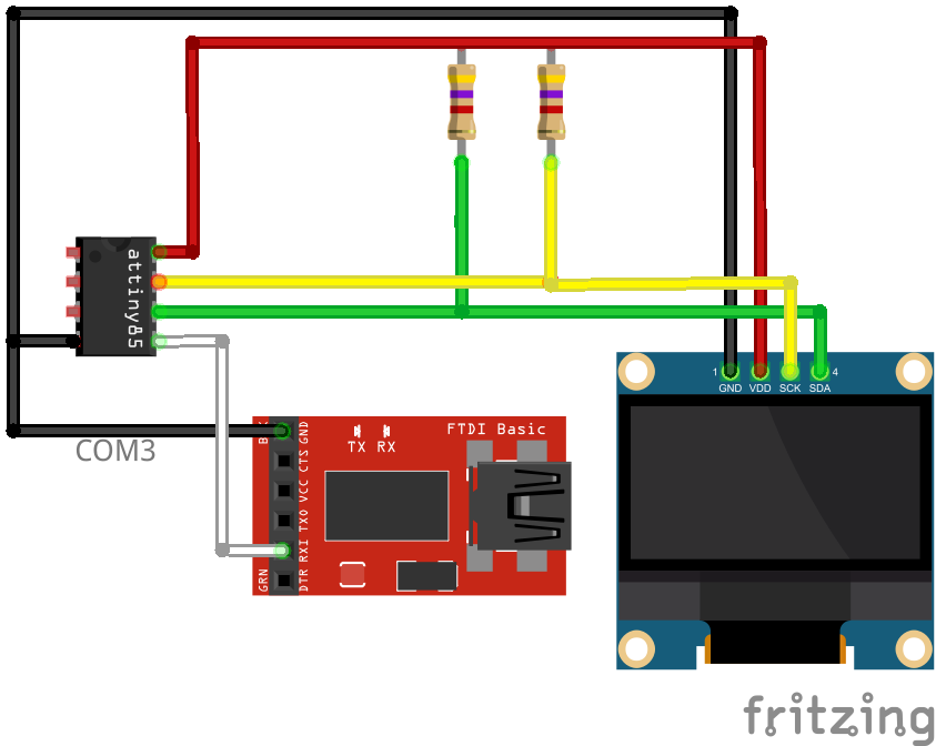
Your wireup diagram doesn’t show the ATTiny being powered by 5V from the FTDI, but I assume that’s just an oversight in the diagram. But more importantly, the pins are wrong? When I read the datasheet
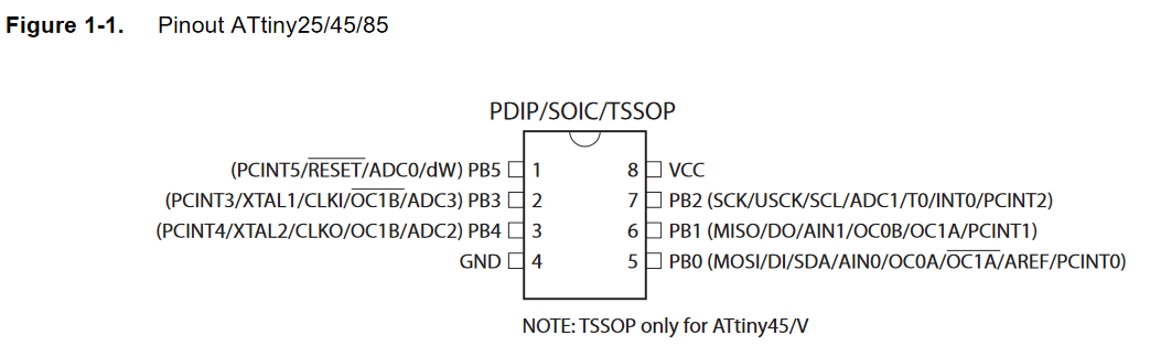
Then again per above posts, PB0 is SDA, PB1 is SCL and PB2 is UART_TX (when also using the code from above, of course). But in your example you’ve connected what is PB0 per datasheet to the UART receiver. Double check these pins.
You would need a special debug probe (maybe an Atmel ICE) and hope that the free debugging tools like Avarice support the chip. Also the ATTiny would need a fuse change to enable debugWire (debug via RESET pin). With Atmel Studio and their proprietary tools it works out of the box, but PlatformIO doesn’t have built-in support for that.
The Attiny85 is mounted on a Sparkfun Tiny AVR programmer. I can see that the pins are wrong but on a pinout image I copied from the web had the pins like I wired them. So you can’t trust things on the web. I changed the wiring, SDA to PB0, SCL to PB2 and TX to PB1, all according to the datasheet. Unfortunately there is no change, compilation and uploading go fine and then nothing. There’s a switch on the FT232R to choose between 5V and 3.3V and I’ve set it to 5V and hope that’s correct.
Yes, since the device is also running at 5V.
Hm, idk, it works fine when using my ATTiny85 on the Digistump. Are you using board = digispark-tiny or doing it with attiny85?
Does the sketch No text on OLED 128x64 from ATTiny85 - #6 by maxgerhardt still function and you get serial output somewhere?
First of all, in my previous reply I should have said ‘SDA to PB0, SCL to PB2 and RX-I to PB1’. I recreated the serial test and disconnected the I2C wires and had the RX-I connected to PB1 as before and it doesn’t work. I moved RX-I to PB0 and that works. When I have SDA and SCL connected on PB0 and PB2 respectively the RX-I have to go to PB1 and that doesn’t work. Can RX-I and SDA share the same pin?
Now I’ve made some progress with the I2C_Scanner sketch. I use SoftwareSerial and set Rx and Tx to 3 and 4 and Serial Monitor works now but the sketch fails on I2C_init(). SCL and SDA are low meaning the bus is busy.
Code:
#define I2C_TIMEOUT 0
#define I2C_NOINTERRUPT 0
#define I2C_FASTMODE 0
#define FAC 1
#define I2C_CPUFREQ (F_CPU/FAC)
#define LED 2

#define SDA_PORT PORTB
#define SDA_PIN 5
#define SCL_PORT PORTB
#define SCL_PIN 7
#define I2C_FASTMODE 0

const int Rx = 3;
const int Tx = 4;

#include <SoftI2CMaster.h>
#include <avr/io.h>
#include <SoftwareSerial.h>

SoftwareSerial ssSerial(Rx, Tx);

void CPUSlowDown(int fac)
{
  // slow down processor by a fac
    CLKPR = _BV(CLKPCE);
    CLKPR = _BV(CLKPS1) | _BV(CLKPS0);
}


void setup(void)
{
  #if FAC != 1
    CPUSlowDown(FAC);
  #endif

  pinMode(Rx, INPUT);
  pinMode(Tx, OUTPUT);
  ssSerial.begin(9600);
  ssSerial.println(F("Intializing ..."));
  ssSerial.print("I2C delay counter: ");
  ssSerial.println(I2C_DELAY_COUNTER);
  if (!i2c_init())
    ssSerial.println(F("Initialization error. SDA or SCL are low"));
  else
    ssSerial.println(F("...done"));
}

void loop(void)
{
  uint8_t add = 0;
  int found = false;
  ssSerial.println("Scanning ...");

  ssSerial.println("       8-bit 7-bit addr");
  // try read
  do
  {
    delay(100);
    if (i2c_start(add | I2C_READ))
    {
      found = true;
      i2c_read(true);
      i2c_stop();
      ssSerial.print("Read:   0x");
      if (add < 0x0F) Serial.print(0, HEX);
      ssSerial.print(add+I2C_READ, HEX);
      ssSerial.print("  0x");
      if (add>>1 < 0x0F) ssSerial.print(0, HEX);
      ssSerial.println(add>>1, HEX);
    }
    else i2c_stop();
    add += 2;
  } while (add);

  // try write
  add = 0;
  do
  {
    if (i2c_start(add | I2C_WRITE)) {
      found = true;
      i2c_stop();
      ssSerial.print("Write:  0x");
      if (add < 0x0F) Serial.print(0, HEX);
      ssSerial.print(add+I2C_WRITE, HEX);
      ssSerial.print("  0x");
      if (add>>1 < 0x0F) ssSerial.print(0, HEX);
      ssSerial.println(add>>1, HEX);
    } else i2c_stop();
    i2c_stop();
    add += 2;
  } while (add);
  if (!found) ssSerial.println(F("No I2C device found."));
  ssSerial.println("Done\n\n");
  delay(1000/FAC);
}
Serial monitor output:
> Executing task in folder I2C_scanner: C:\Users\hans\.platformio\penv\Scripts\platformio.exe device monitor <

--- Available filters and text transformations: colorize, debug, default, direct, hexlify, log2file, nocontrol, printable, send_on_enter, time
--- More details at http://bit.ly/pio-monitor-filters
--- Miniterm on COM3  9600,8,N,1 ---
--- Quit: Ctrl+C | Menu: Ctrl+T | Help: Ctrl+T followed by Ctrl+H ---
Intializing ...
I2C delay counter: 8
Initialization error. SDA or SCL are low
Scanning ...
8-bit 7-bit addrNo, they must be electrically different signals. But the I2C driver is in software anyways, you can arbitrarily change the SCL and SDA pins in both I2C scanner sketch and OLED sketch.
You have designated here PB7 as SCL? But that pins is not exposed on the ATTiny85? Per diagrams above it’s between PB0 and PB5 (and PB5 can also be the reset pin). Try with two arbitrary different pins with no overlap and place the pullup resistors there.
Yes, I keep forgetting the pin designations. I changed them to default 2 and 0 and now it runs through all addresses and WRITEs out 0x00 and 0x01. I suppose those are the addresses it has found on the bus. It is not the OLED though. There’s an initialization error but it seems to work just the same.
> Executing task in folder I2C_scanner: C:\Users\hans\.platformio\penv\Scripts\platformio.exe device monitor <

--- Available filters and text transformations: colorize, debug, default, direct, hexlify, log2file, nocontrol, printable, send_on_enter, time
--- More details at http://bit.ly/pio-monitor-filters
--- Miniterm on COM3  9600,8,N,1 ---
--- Quit: Ctrl+C | Menu: Ctrl+T | Help: Ctrl+T followed by Ctrl+H ---
Intializing ...
I2C delay counter: 8
Initialization error. SDA or SCL are low
Scanning ...
       8-bit 7-bit addr
Read:   0x1  0x00
Read:   0x3  0x01
Read:   0x5  0x02
Read:   0x7  0x03
Read:   0x9  0x04

  etcetera ...

Read:   0xF7  0x7B
Read:   0xF9  0x7C
Read:   0xFB  0x7D
Read:   0xFD  0x7E
Read:   0xFF  0x7F
Write:  0x0  0x00
Write:  0x2  0x01
DoneThe pins are still low. Are the pullups placed correctly on the two pins? Can you measure the voltage there at SCL and SDA with respect to GND to make sure it’s +5V?
I checked the pullup resistors - 4.7kΩ Voltages: SDA-GND 2.1V, SCL-GND 3-8V When I remove the OLED display SDA-GND is 2.1V, SCL-GND 5V.
That is very weird. SDA still seems to be floating and SCL seems to be… held down by the OLED screen?
If you remove the OLED screen and just have the pullups on the SDA and SCL lines, both should be reading 5V, except if SDA and SCL are purposefully held low by something.
Can you double check that on one end of the resistor that should go to +5V, you do really get +5V?
With OLED removed SCL measures 5V and SDA 2.1V. On the other side of the pullups I have 5V I tested two fresh, unused ATtiny85s and uploaded and the serial monitor output was totally garbled, backward question marks and other unintelligible stuff. Total mystery.
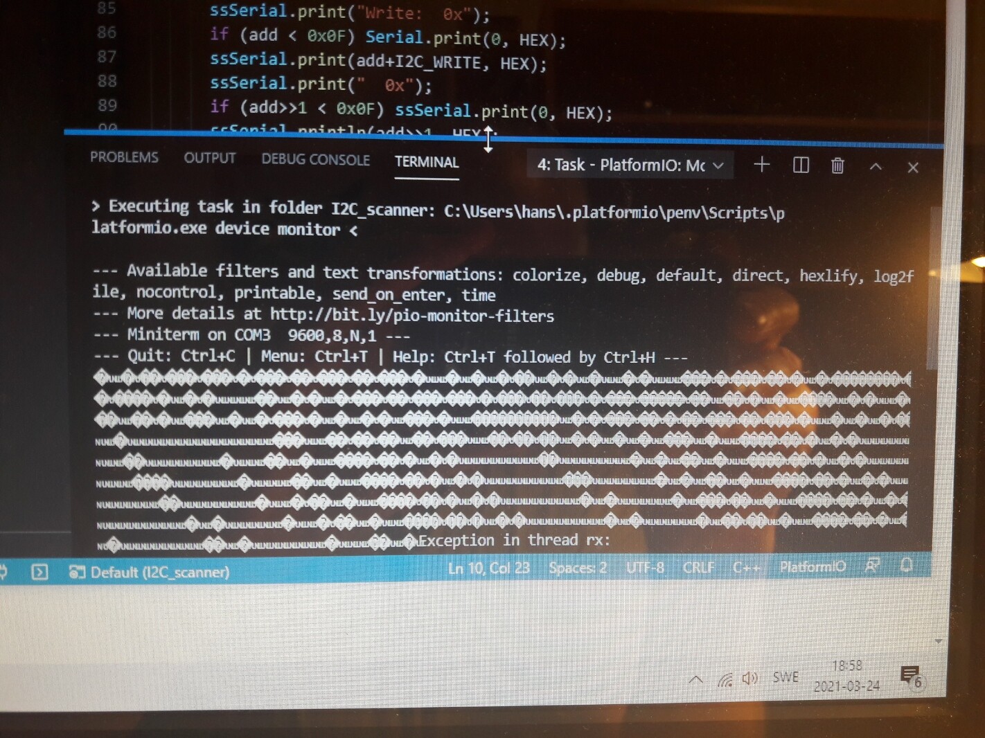
The “Exception in thread RX” indicates that something is going wrong with the serial adapter. It’s set for 5V input? And only has GND + RX connected to GND + TX? Or, the adapter itself is failing…
No, the exception is Rx is when I pull the USB plugs from the PC.
Ah. Hm, either the RX line is just floating and pickup up random noise or it’s running at the wrong clockspeed. You may try a few monitor_speed at e.g. half or double of 9600. Which is however really weird if you were able to get UART output just a second ago. This setup seems haunted. All I had to do to get it working was install 2 pullup resistors and the I2C and Serial worked without problems ![]()
What about two new ATTinys giving the strange output? Has the Sparkfun programmer set any fuses or made any changes to the Tiny that works but not to the new ones?
The programmer itself doesn’t set the fuses, it always gets set via avrdude. But your board may have different than expected fuses set?
You can try the project task
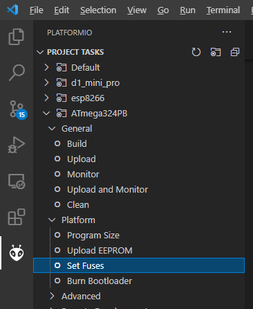
Error: Dynamic fuses generation for attiny85 is not supported. Please specify fuses in platformio.ini