So what pins is the OLED display connected to? The original code wants you to do
Since I don’t see IO16 or IO17 on the diagram, just use different ones like IO15, IO14.
And if if it still doesn’t show anything you might want to change the 0x3C to 0x3D (some displays have that). If that still doesn’t work run the I2C scanner sketch first to ensure the OLED is seen at all.
I already changed the IO pins.
The pins numbering not always reprisents the IO number which is somewhat confusing.
I need four pins:
- SDA is pin 18 = IO4
- SCL is pin 19 = IO2
- Switch to toggle between SerialConfig and NTPserver mode is pin 17 = IO35
- Is for onboard LED which is not available on the WT32-ETH01 board, I use pin 16 = IO12 instead.
//i2c bus pins
#define SDApin 18 // IO4
#define SCLpin 19 // IO2

//initialize i2C OLED on esp32 I2C0 (pins 16 and 17)  <- pins for Olimex board
SSD1306 display(0x3C, SDApin, SCLpin); // Addr, SDA, SCL
#define lcdOffsetUpper 8 // width in number of pixels for upper free space on lcd
#define lcdOffsetLeft 4 // width in number of pixels for left free space on lcd

// rocking switch connecting pin 5 with high/low; toggles between serialConfig/NTPserver mode
#define SWITCH_PIN 17 // IO35 = input only
static bool SerialMirror = 0;

// built-in LED for Olimex (not available on WT32-ETH01) I use pin 16 / IO12 instead
#define LED_PIN 16 // IO12
But I’m gonna try the I2C Scanner sketch you mention to make sure.
…no? When you specify 18 here, that is IO18. IO18 is not broken out. You always select the IOx number here, not “the nth pin on the dev board”.
Now you even get me more confused ![]()
I’m gonna reverse engineer the tracks from the WT32-S1 and see what is broken out to which pin of the WT32-ETH01 board.
Noob question:
Is there somewhere a conversion table in Platformio that tell us what board PIN belongs to which IO WT32-S1 ?
Or do we need to define IO number instead of PIN number ? (I’m just loud thinking here)
That’s exactly what I’m trying to tell you.
The OLED display is working fine now.
I have define all the IO ports I needed for this project:
IO15 = GPS-Time-Pulse
IO5 = GPS-RX
IO17 = GPS-TX
IO4 = SDA OLED
IO2 = SCL OLED
IO35 = Switch
IO12 = LED
The board seems not to boot fully up, it restarts over and over again (bootloop I think).
Don’t know if it is a hardware or software thing.
This is the serial output:
NTP Server started.
ets Jun  8 2016 00:22:57

rst:0x8 (TG1WDT_SYS_RESET),boot:0x13 (SPI_FAST_FLASH_BOOT)
configsip: 0, SPIWP:0xee
clk_drv:0x00,q_drv:0x00,d_drv:0x00,cs0_drv:0x00,hd_drv:0x00,wp_drv:0x00
mode:DIO, clock div:1
load:0x3fff0030,len:1344
load:0x40078000,len:13836
load:0x40080400,len:3608
entry 0x400805f0
E (6) gpio: gpio_set_level(226): GPIO output gpio_num error
How can I trace such error ?
There is still some code referencing pin 226, which is extremely high. Can you reupload the full project you have now?
Specifically you’re running into
Do you mean you want a full copy of my current project folder ?
If yes, what is the best way to share this as I can not upload a compressed RAR here of 12mb size.
You can delete the .pio folder which holds the temporary compiled files. Only the source code matters.
You could use Google Drive, Dropbox, https://www.file.io/, etc…
Ik have deleted all in the ‘.pio’ folder.
I never use such services like Dropbox etc… so I have made an account.
Hope the link works:
Let me know if it works.
Download works, but nothing really looks out of place in terms of pin definitions…
Can you add more Serial.println("step: .."); statements after each step in setup() so that we can see which call causes the error message to appear?
Sorry I don’t understand what I have to do, I’m a totally noob at this ![]()
I have done some reading and I think I understand.
At serval places I added Serial.println to have serial output to determine where it goes wrong at which point.
Unfortunately it give nothing extra at the output:
NTP Server started.
ets Jun  8 2016 00:22:57

rst:0x8 (TG1WDT_SYS_RESET),boot:0x13 (SPI_FAST_FLASH_BOOT)
configsip: 0, SPIWP:0xee
clk_drv:0x00,q_drv:0x00,d_drv:0x00,cs0_drv:0x00,hd_drv:0x00,wp_drv:0x00
mode:DIO, clock div:1
load:0x3fff0030,len:1344
load:0x40078000,len:13836
load:0x40080400,len:3608
entry 0x400805f0
E (6) gpio: gpio_set_level(226): GPIO output gpio_num error
The board is working fine otherwise, I tested a blink sketch with a LED on pin-2 and it works.
So the code must be responsible for the not booting issue.
I have change serval values of pin difinitions and now this ‘gpio_num error’ is gone.
GPS-Pulse IO33
GPS-RX IO35
GPS-TX IO17
SDA IO4
SCL IO2
Switch IO14
LED IO12
Still it won’t boot, it starts all over again.
This is now how it looks:
NTP Server started.
ets Jun  8 2016 00:22:57

rst:0x8 (TG1WDT_SYS_RESET),boot:0x13 (SPI_FAST_FLASH_BOOT)
configsip: 0, SPIWP:0xee
clk_drv:0x00,q_drv:0x00,d_drv:0x00,cs0_drv:0x00,hd_drv:0x00,wp_drv:0x00
mode:DIO, clock div:1
load:0x3fff0030,len:1344
load:0x40078000,len:13836
load:0x40080400,len:3608
entry 0x400805f0
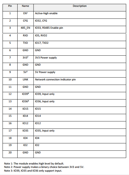
Conflict with Ethernet, I2C works only with: IO32 (marked on the board as CFG, “pin 2” according to page 9 of http://www.wireless-tag.com/wp-content/uploads/2022/10/WT32-ETH01_datasheet_V1.3-en.pdf) configured as SCL; IO33 (marked on the board as 485_EN, “pin 3” ibid.) configured as SDA.
Thanks for your awareness.
However I set IO33 (pin5) to SCL and SDA to IO32 (pin3) but this did not helped.
//i2c bus pins
#define SDApin 32
#define SCLpin 33
It still not want to boot up.
How is the device powered?
I is powered by a Professional Regulated Power Supply 0-30v 0-3A.
The power is not the problem as other code does work okay on it.
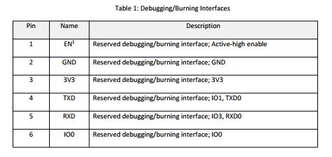
Also there have been reported that the board has power up issues and could be solved by connecting a 470µF capacitor between EN pin-1 and GND pin-3 which delays boot, I have tried this also but did nothing.
It must be in the code.
I just tested another code of a GPS NTP Server project that is written for this WT32-ETH01 board and it works pkay, although this projec uses a ST7735 display which I don’t have but the serial output shows that it works.
This is the serial output:
--- Terminal on COM5 | 115200 8-N-1
--- Available filters and text transformations: colorize, debug, default, direct, esp32_exception_decoder, hexlify, log2file, nocontrol, printable, send_on_enter, time
--- More details at https://bit.ly/pio-monitor-filters
--- Quit: Ctrl+C | Menu: Ctrl+T | Help: Ctrl+T followed by Ctrl+H
No GPS data or PPS pulse was received in the past 5 seconds.
No GPS data or PPS pulse was received in the past 5 seconds.
No GPS data or PPS pulse was received in the past 5 seconds.
E (214207) esp_netif_lwip: esp_netif_new: Failed to configure netif with config=0x3ffb26d0 (config or if_key is NULL or duplicate key)
E (214209) esp.emac: esp_eth_mac_new_esp32(595): alloc emac interrupt failed
[214235][E][ETH.cpp:267] begin(): esp_eth_mac_new_esp32 failed
No GPS data or PPS pulse was received in the past 5 seconds.
No GPS data or PPS pulse was received in the past 5 seconds.
No GPS data or PPS pulse was received in the past 5 seconds.
No GPS data or PPS pulse was received in the past 5 seconds.
No GPS data or PPS pulse was received in the past 5 seconds.
E (218707) esp_netif_lwip: esp_netif_new: Failed to configure netif with config=0x3ffb26d0 (config or if_key is NULL or duplicate key)
E (218709) esp.emac: esp_eth_mac_new_esp32(595): alloc emac interrupt failed
[218735][E][ETH.cpp:267] begin(): esp_eth_mac_new_esp32 failed
No GPS data or PPS pulse was received in the past 5 seconds.
No GPS data or PPS pulse was received in the past 5 seconds.
In this projects all these IO pins were used:
Wiring
GPS <-> WT32-ETH01
-----------------
GND --> GND
Tx  --> PIN35 (Rx)
Rx  --> PIN17 (Tx)
PPS --> PIN33
VCC --> +5V

TFT <-> WT32-ETH01
-----------------
GND  --> GND
VCC  --> +5V
BLK  --> +5V
#MISO --> PIN36
MOSI --> PIN15
SCLK --> PIN14
DC   --> PIN4
CS   --> PIN12
RST  --> PIN2
So it is very certain that the code is the problem.
If I only knew how I could change the code to use the SSD1306 instead the ST7735 display.