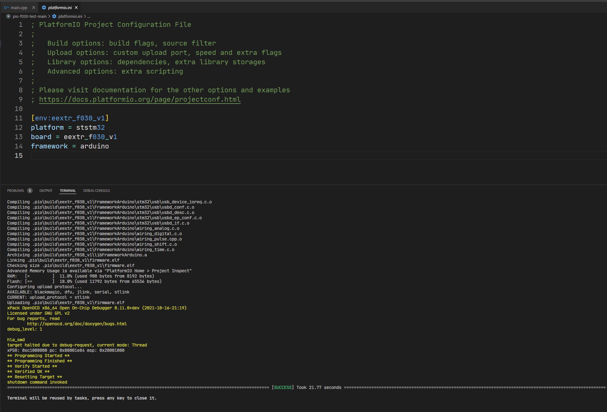
Can you download + test
?
The speed might still be off by factor 2 though.
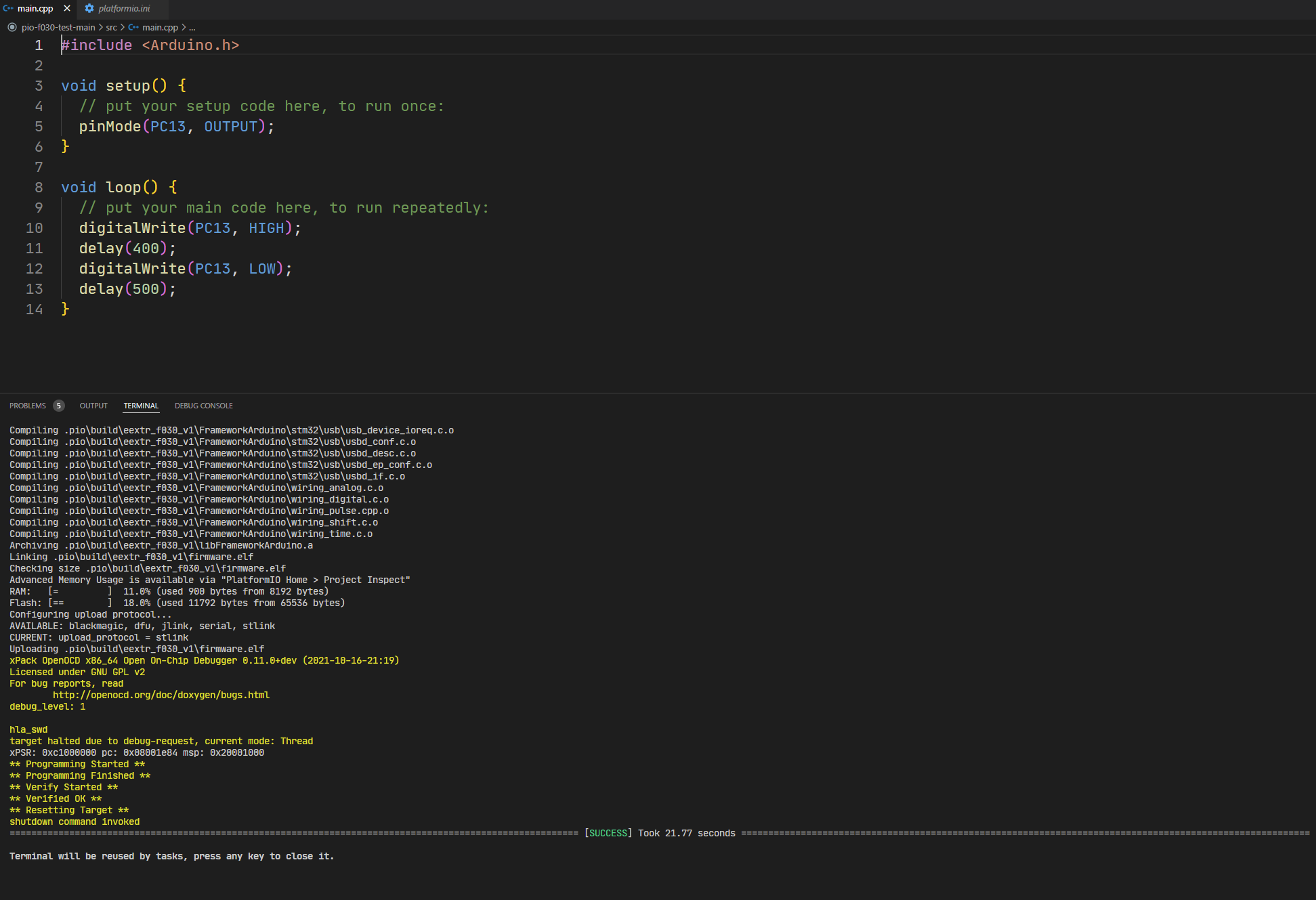
Can you download + test
?
The speed might still be off by factor 2 though.
In the left sidebar you should have a debug icon, then a play button. Can you see whether code execution is stuck somewhere?
This may need
debug_tool = stlink
in the platformio.ini
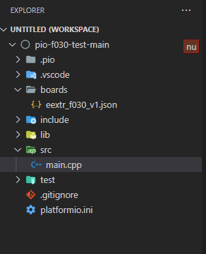
board have file
/*
 *******************************************************************************
 * Copyright (c) 2020, STMicroelectronics
 * All rights reserved.
 *
 * This software component is licensed by ST under BSD 3-Clause license,
 * the "License"; You may not use this file except in compliance with the
 * License. You may obtain a copy of the License at:
 *                        opensource.org/licenses/BSD-3-Clause
 *
 *******************************************************************************
 * Automatically generated from STM32F031K6Tx.xml
 */
#include "Arduino.h"
#include "PeripheralPins.h"

/* =====
 * Note: Commented lines are alternative possibilities which are not used per default.
 *       If you change them, you will have to know what you do
 * =====
 */

//*** ADC ***

#ifdef HAL_ADC_MODULE_ENABLED
WEAK const PinMap PinMap_ADC[] = {
  {PA_0,  ADC1,  STM_PIN_DATA_EXT(STM_MODE_ANALOG, GPIO_NOPULL, 0, 0, 0)}, // ADC_IN0
  {PA_1,  ADC1,  STM_PIN_DATA_EXT(STM_MODE_ANALOG, GPIO_NOPULL, 0, 1, 0)}, // ADC_IN1
  {PA_2,  ADC1,  STM_PIN_DATA_EXT(STM_MODE_ANALOG, GPIO_NOPULL, 0, 2, 0)}, // ADC_IN2 // Connected to STLink Tx
  {PA_3,  ADC1,  STM_PIN_DATA_EXT(STM_MODE_ANALOG, GPIO_NOPULL, 0, 3, 0)}, // ADC_IN3
  {PA_4,  ADC1,  STM_PIN_DATA_EXT(STM_MODE_ANALOG, GPIO_NOPULL, 0, 4, 0)}, // ADC_IN4
  {PA_5,  ADC1,  STM_PIN_DATA_EXT(STM_MODE_ANALOG, GPIO_NOPULL, 0, 5, 0)}, // ADC_IN5
  {PA_6,  ADC1,  STM_PIN_DATA_EXT(STM_MODE_ANALOG, GPIO_NOPULL, 0, 6, 0)}, // ADC_IN6
  {PA_7,  ADC1,  STM_PIN_DATA_EXT(STM_MODE_ANALOG, GPIO_NOPULL, 0, 7, 0)}, // ADC_IN7
  {PB_0,  ADC1,  STM_PIN_DATA_EXT(STM_MODE_ANALOG, GPIO_NOPULL, 0, 8, 0)}, // ADC_IN8
  {PB_1,  ADC1,  STM_PIN_DATA_EXT(STM_MODE_ANALOG, GPIO_NOPULL, 0, 9, 0)}, // ADC_IN9
  {NC,    NP,    0}
};
#endif

//*** No DAC ***

//*** I2C ***

#ifdef HAL_I2C_MODULE_ENABLED
WEAK const PinMap PinMap_I2C_SDA[] = {
  {PA_10, I2C1, STM_PIN_DATA(STM_MODE_AF_OD, GPIO_NOPULL, GPIO_AF4_I2C1)},
  {PB_7,  I2C1, STM_PIN_DATA(STM_MODE_AF_OD, GPIO_NOPULL, GPIO_AF1_I2C1)},
  {NC,    NP,    0}
};
#endif

#ifdef HAL_I2C_MODULE_ENABLED
WEAK const PinMap PinMap_I2C_SCL[] = {
  {PA_9,  I2C1, STM_PIN_DATA(STM_MODE_AF_OD, GPIO_NOPULL, GPIO_AF4_I2C1)},
  {PB_6,  I2C1, STM_PIN_DATA(STM_MODE_AF_OD, GPIO_NOPULL, GPIO_AF1_I2C1)},
  {NC,    NP,    0}
};
#endif

//*** PWM ***

#ifdef HAL_TIM_MODULE_ENABLED
WEAK const PinMap PinMap_PWM[] = {
  {PA_0,  TIM2,   STM_PIN_DATA_EXT(STM_MODE_AF_PP, GPIO_PULLUP, GPIO_AF2_TIM2, 1, 0)}, // TIM2_CH1
  {PA_1,  TIM2,   STM_PIN_DATA_EXT(STM_MODE_AF_PP, GPIO_PULLUP, GPIO_AF2_TIM2, 2, 0)}, // TIM2_CH2
  {PA_2,  TIM2,   STM_PIN_DATA_EXT(STM_MODE_AF_PP, GPIO_PULLUP, GPIO_AF2_TIM2, 3, 0)}, // TIM2_CH3 // Connected to STLink Tx
  {PA_3,  TIM2,   STM_PIN_DATA_EXT(STM_MODE_AF_PP, GPIO_PULLUP, GPIO_AF2_TIM2, 4, 0)}, // TIM2_CH4
  {PA_4,  TIM14,  STM_PIN_DATA_EXT(STM_MODE_AF_PP, GPIO_PULLUP, GPIO_AF4_TIM14, 1, 0)}, // TIM14_CH1
  {PA_5,  TIM2,   STM_PIN_DATA_EXT(STM_MODE_AF_PP, GPIO_PULLUP, GPIO_AF2_TIM2, 1, 0)}, // TIM2_CH1
  {PA_6,  TIM3,   STM_PIN_DATA_EXT(STM_MODE_AF_PP, GPIO_PULLUP, GPIO_AF1_TIM3, 1, 0)}, // TIM3_CH1
  //  {PA_6,  TIM16,  STM_PIN_DATA_EXT(STM_MODE_AF_PP, GPIO_PULLUP, GPIO_AF5_TIM16, 1, 0)}, // TIM16_CH1
  {PA_7,  TIM1,   STM_PIN_DATA_EXT(STM_MODE_AF_PP, GPIO_PULLUP, GPIO_AF2_TIM1, 1, 1)}, // TIM1_CH1N
  //  {PA_7,  TIM3,   STM_PIN_DATA_EXT(STM_MODE_AF_PP, GPIO_PULLUP, GPIO_AF1_TIM3, 2, 0)}, // TIM3_CH2
  //  {PA_7,  TIM14,  STM_PIN_DATA_EXT(STM_MODE_AF_PP, GPIO_PULLUP, GPIO_AF4_TIM14, 1, 0)}, // TIM14_CH1
  //  {PA_7,  TIM17,  STM_PIN_DATA_EXT(STM_MODE_AF_PP, GPIO_PULLUP, GPIO_AF5_TIM17, 1, 0)}, // TIM17_CH1
  {PA_8,  TIM1,   STM_PIN_DATA_EXT(STM_MODE_AF_PP, GPIO_PULLUP, GPIO_AF2_TIM1, 1, 0)}, // TIM1_CH1
  {PA_9,  TIM1,   STM_PIN_DATA_EXT(STM_MODE_AF_PP, GPIO_PULLUP, GPIO_AF2_TIM1, 2, 0)}, // TIM1_CH2
  {PA_10, TIM1,   STM_PIN_DATA_EXT(STM_MODE_AF_PP, GPIO_PULLUP, GPIO_AF2_TIM1, 3, 0)}, // TIM1_CH3
  {PA_11, TIM1,   STM_PIN_DATA_EXT(STM_MODE_AF_PP, GPIO_PULLUP, GPIO_AF2_TIM1, 4, 0)}, // TIM1_CH4
  {PA_13, NC,   STM_PIN_DATA_EXT(STM_MODE_AF_PP,
GPIO_PULLUP, 0, 0, 0)}, //
  {PA_14, NC,   STM_PIN_DATA_EXT(STM_MODE_AF_PP,
GPIO_PULLUP, 0, 0, 0)}, //
  {PA_15, TIM2,   STM_PIN_DATA_EXT(STM_MODE_AF_PP, GPIO_PULLUP, GPIO_AF2_TIM2, 1, 0)}, // TIM2_CH1 // Connected to STLink Rx
  //  {PB_0,  TIM1,   STM_PIN_DATA_EXT(STM_MODE_AF_PP, GPIO_PULLUP, GPIO_AF2_TIM1, 2, 1)}, // TIM1_CH2N
  {PB_0,  TIM3,   STM_PIN_DATA_EXT(STM_MODE_AF_PP, GPIO_PULLUP, GPIO_AF1_TIM3, 3, 0)}, // TIM3_CH3
  //  {PB_1,  TIM1,   STM_PIN_DATA_EXT(STM_MODE_AF_PP, GPIO_PULLUP, GPIO_AF2_TIM1, 3, 1)}, // TIM1_CH3N
  {PB_1,  TIM3,   STM_PIN_DATA_EXT(STM_MODE_AF_PP, GPIO_PULLUP, GPIO_AF1_TIM3, 4, 0)}, // TIM3_CH4
  //  {PB_1,  TIM14,  STM_PIN_DATA_EXT(STM_MODE_AF_PP, GPIO_PULLUP, GPIO_AF0_TIM14, 1, 0)}, // TIM14_CH1
 {PB_2,  NC,   STM_PIN_DATA_EXT(STM_MODE_AF_PP,
GPIO_PULLUP, 0, 0, 0)}, // 0
  {PB_3,  TIM2,   STM_PIN_DATA_EXT(STM_MODE_AF_PP, GPIO_PULLUP, GPIO_AF2_TIM2, 2, 0)}, // TIM2_CH2
  {PB_4,  TIM3,   STM_PIN_DATA_EXT(STM_MODE_AF_PP, GPIO_PULLUP, GPIO_AF1_TIM3, 1, 0)}, // TIM3_CH1
  {PB_5,  TIM3,   STM_PIN_DATA_EXT(STM_MODE_AF_PP, GPIO_PULLUP, GPIO_AF1_TIM3, 2, 0)}, // TIM3_CH2
  {PB_6,  TIM16,  STM_PIN_DATA_EXT(STM_MODE_AF_PP, GPIO_PULLUP, GPIO_AF2_TIM16, 1, 1)}, // TIM16_CH1N
  {PB_7,  TIM17,  STM_PIN_DATA_EXT(STM_MODE_AF_PP,
GPIO_PULLUP, GPIO_AF2_TIM17, 1, 1)}, // TIM16_CH1N
  {PB_8,  TIM16,  STM_PIN_DATA_EXT(STM_MODE_AF_PP,
GPIO_PULLUP, GPIO_AF2_TIM16, 1, 0)}, // TIM16_CH1
  {PB_9,  TIM17,  STM_PIN_DATA_EXT(STM_MODE_AF_PP,
GPIO_PULLUP, GPIO_AF2_TIM17, 1, 0)}, // TIM17_CH1
  {PB_10,  TIM2,  STM_PIN_DATA_EXT(STM_MODE_AF_PP,
GPIO_PULLUP, GPIO_AF2_TIM2, 3, 0)}, // TIM2_CH3
  {PB_11,  TIM2,  STM_PIN_DATA_EXT(STM_MODE_AF_PP,
GPIO_PULLUP, GPIO_AF2_TIM2, 4, 0)}, // TIM2_CH4
  {PB_12,  NC,  STM_PIN_DATA_EXT(STM_MODE_AF_PP,
GPIO_PULLUP, GPIO_AF2_TIM1, 0, 0)}, // TIM16_CH1
  {PB_13,  TIM16,  STM_PIN_DATA_EXT(STM_MODE_AF_PP,
GPIO_PULLUP, GPIO_AF2_TIM16, 1, 0)}, // TIM16_CH1
  {PB_14,  TIM16,  STM_PIN_DATA_EXT(STM_MODE_AF_PP,
GPIO_PULLUP, GPIO_AF2_TIM16, 1, 0)}, // TIM16_CH1
  {PB_15,  TIM16,  STM_PIN_DATA_EXT(STM_MODE_AF_PP,
GPIO_PULLUP, GPIO_AF2_TIM16, 1, 0)}, // TIM16_CH1
  {PC_13,  NC,  STM_PIN_DATA_EXT(STM_MODE_AF_PP,
GPIO_PULLUP, 0, 0, 0)}, // LED
  {PC_14,  NC,  STM_PIN_DATA_EXT(STM_MODE_AF_PP,
GPIO_PULLUP, 0, 0, 0)}, //
  {PC_15,  NC,  STM_PIN_DATA_EXT(STM_MODE_AF_PP,
GPIO_PULLUP, 0, 0, 0)}, //
  {PF_6,  NC,  STM_PIN_DATA_EXT(STM_MODE_AF_PP,
GPIO_PULLUP, 0, 0, 0)}, //
  {PF_7,  NC,  STM_PIN_DATA_EXT(STM_MODE_AF_PP,
GPIO_PULLUP, 0, 0, 0)}, //
  {NC,    NP,    0}

};
#endif

//*** SERIAL ***

#ifdef HAL_UART_MODULE_ENABLED
WEAK const PinMap PinMap_UART_TX[] = {
  {PA_2,  USART1,  STM_PIN_DATA(STM_MODE_AF_PP, GPIO_PULLUP, GPIO_AF1_USART1)}, // Connected to STLink Rx
  {PA_9,  USART1,  STM_PIN_DATA(STM_MODE_AF_PP, GPIO_PULLUP, GPIO_AF1_USART1)},
  {PA_14, USART1,  STM_PIN_DATA(STM_MODE_AF_PP, GPIO_PULLUP, GPIO_AF1_USART1)}, // Connected to SWCLK
  {PB_6,  USART1,  STM_PIN_DATA(STM_MODE_AF_PP, GPIO_PULLUP, GPIO_AF0_USART1)},
  {NC,    NP,    0}
};
#endif

#ifdef HAL_UART_MODULE_ENABLED
WEAK const PinMap PinMap_UART_RX[] = {
  {PA_3,  USART1,  STM_PIN_DATA(STM_MODE_AF_PP, GPIO_PULLUP, GPIO_AF1_USART1)},
  {PA_10, USART1,  STM_PIN_DATA(STM_MODE_AF_PP, GPIO_PULLUP, GPIO_AF1_USART1)},
  {PA_15, USART1,  STM_PIN_DATA(STM_MODE_AF_PP, GPIO_PULLUP, GPIO_AF1_USART1)}, // Connected to STLink Rx
  {PB_7,  USART1,  STM_PIN_DATA(STM_MODE_AF_PP, GPIO_PULLUP, GPIO_AF0_USART1)},
  {NC,    NP,    0}
};
#endif

#ifdef HAL_UART_MODULE_ENABLED
WEAK const PinMap PinMap_UART_RTS[] = {
  {PA_1,  USART1,  STM_PIN_DATA(STM_MODE_AF_PP, GPIO_PULLUP, GPIO_AF1_USART1)},
  {PA_12, USART1,  STM_PIN_DATA(STM_MODE_AF_PP, GPIO_PULLUP, GPIO_AF1_USART1)},
  {NC,    NP,    0}
};
#endif

#ifdef HAL_UART_MODULE_ENABLED
WEAK const PinMap PinMap_UART_CTS[] = {
  {PA_0,  USART1,  STM_PIN_DATA(STM_MODE_AF_PP, GPIO_PULLUP, GPIO_AF1_USART1)},
  {PA_11, USART1,  STM_PIN_DATA(STM_MODE_AF_PP, GPIO_PULLUP, GPIO_AF1_USART1)},
  {NC,    NP,    0}
};
#endif

//*** SPI ***

#ifdef HAL_SPI_MODULE_ENABLED
WEAK const PinMap PinMap_SPI_MOSI[] = {
  {PA_7,  SPI1, STM_PIN_DATA(STM_MODE_AF_PP, GPIO_PULLUP, GPIO_AF0_SPI1)},
  {PB_5,  SPI1, STM_PIN_DATA(STM_MODE_AF_PP, GPIO_PULLUP, GPIO_AF0_SPI1)},
  {NC,    NP,    0}
};
#endif

#ifdef HAL_SPI_MODULE_ENABLED
WEAK const PinMap PinMap_SPI_MISO[] = {
  {PA_6,  SPI1, STM_PIN_DATA(STM_MODE_AF_PP, GPIO_PULLUP, GPIO_AF0_SPI1)},
  {PB_4,  SPI1, STM_PIN_DATA(STM_MODE_AF_PP, GPIO_PULLUP, GPIO_AF0_SPI1)},
  {NC,    NP,    0}
};
#endif

#ifdef HAL_SPI_MODULE_ENABLED
WEAK const PinMap PinMap_SPI_SCLK[] = {
  {PA_5,  SPI1, STM_PIN_DATA(STM_MODE_AF_PP, GPIO_PULLUP, GPIO_AF0_SPI1)},
  {PB_3,  SPI1, STM_PIN_DATA(STM_MODE_AF_PP, GPIO_PULLUP, GPIO_AF0_SPI1)},
  {NC,    NP,    0}
};
#endif

#ifdef HAL_SPI_MODULE_ENABLED
WEAK const PinMap PinMap_SPI_SSEL[] = {
  {PA_4,  SPI1, STM_PIN_DATA(STM_MODE_AF_PP, GPIO_PULLUP, GPIO_AF0_SPI1)},
  {PA_15, SPI1, STM_PIN_DATA(STM_MODE_AF_PP, GPIO_PULLUP, GPIO_AF0_SPI1)}, // Connected to STLink Rx
  {NC,    NP,    0}
};
#endif

//*** No CAN ***

//*** No ETHERNET ***

//*** No QUADSPI ***

//*** No USB ***

//*** No SD ***
/**
******************************************************************************
* @file LinkerScript.ld
* @author Auto-generated by STM32CubeIDE
* Abstract : Linker script for NUCLEO-F031K6 Board embedding STM32F031K6Tx Device from stm32f0 series
* 32Kbytes FLASH
* 4Kbytes RAM
*
* Set heap size, stack size and stack location according
* to application requirements.
*
* Set memory bank area and size if external memory is used
******************************************************************************
* @attention
*
* <h2><center>© Copyright (c) 2020 STMicroelectronics.
* All rights reserved.</center></h2>
*
* This software component is licensed by ST under BSD 3-Clause license,
* the "License"; You may not use this file except in compliance with the
* License. You may obtain a copy of the License at:
* opensource.org/licenses/BSD-3-Clause
*
******************************************************************************
*/
/* Entry Point */
ENTRY(Reset_Handler)
/* Highest address of the user mode stack */
_estack = ORIGIN(RAM) + LENGTH(RAM); /* end of "RAM" Ram type memory */
_Min_Heap_Size = 0x200 ; /* required amount of heap */
_Min_Stack_Size = 0x400 ; /* required amount of stack */
/* Memories definition */
MEMORY
{
RAM (xrw) : ORIGIN = 0x20000000, LENGTH = 4K
FLASH (rx) : ORIGIN = 0x8000000, LENGTH = 32K
}
/* Sections */
SECTIONS
{
/* The startup code into "FLASH" Rom type memory */
.isr_vector :
{
. = ALIGN(4);
KEEP(*(.isr_vector)) /* Startup code */
. = ALIGN(4);
} >FLASH
/* The program code and other data into "FLASH" Rom type memory */
.text :
{
. = ALIGN(4);
*(.text) /* .text sections (code) */
*(.text*) /* .text* sections (code) */
*(.glue_7) /* glue arm to thumb code */
*(.glue_7t) /* glue thumb to arm code */
*(.eh_frame)
KEEP (*(.init))
KEEP (*(.fini))
. = ALIGN(4);
_etext = .; /* define a global symbols at end of code */
} >FLASH
/* Constant data into "FLASH" Rom type memory */
.rodata :
{
. = ALIGN(4);
*(.rodata) /* .rodata sections (constants, strings, etc.) */
*(.rodata*) /* .rodata* sections (constants, strings, etc.) */
. = ALIGN(4);
} >FLASH
.ARM.extab : {
. = ALIGN(4);
*(.ARM.extab* .gnu.linkonce.armextab.*)
. = ALIGN(4);
} >FLASH
.ARM : {
. = ALIGN(4);
__exidx_start = .;
*(.ARM.exidx*)
__exidx_end = .;
. = ALIGN(4);
} >FLASH
.preinit_array :
{
. = ALIGN(4);
PROVIDE_HIDDEN (__preinit_array_start = .);
KEEP (*(.preinit_array*))
PROVIDE_HIDDEN (__preinit_array_end = .);
. = ALIGN(4);
} >FLASH
.init_array :
{
. = ALIGN(4);
PROVIDE_HIDDEN (__init_array_start = .);
KEEP (*(SORT(.init_array.*)))
KEEP (*(.init_array*))
PROVIDE_HIDDEN (__init_array_end = .);
. = ALIGN(4);
} >FLASH
.fini_array :
{
. = ALIGN(4);
PROVIDE_HIDDEN (__fini_array_start = .);
KEEP (*(SORT(.fini_array.*)))
KEEP (*(.fini_array*))
PROVIDE_HIDDEN (__fini_array_end = .);
. = ALIGN(4);
} >FLASH
/* Used by the startup to initialize data */
_sidata = LOADADDR(.data);
/* Initialized data sections into "RAM" Ram type memory */
.data :
{
. = ALIGN(4);
_sdata = .; /* create a global symbol at data start */
*(.data) /* .data sections */
*(.data*) /* .data* sections */
. = ALIGN(4);
_edata = .; /* define a global symbol at data end */
} >RAM AT> FLASH
/* Uninitialized data section into "RAM" Ram type memory */
. = ALIGN(4);
.bss :
{
/* This is used by the startup in order to initialize the .bss section */
_sbss = .; /* define a global symbol at bss start */
__bss_start__ = _sbss;
*(.bss)
*(.bss*)
*(COMMON)
. = ALIGN(4);
_ebss = .; /* define a global symbol at bss end */
__bss_end__ = _ebss;
} >RAM
/* User_heap_stack section, used to check that there is enough "RAM" Ram type memory left */
._user_heap_stack :
{
. = ALIGN(8);
PROVIDE ( end = . );
PROVIDE ( _end = . );
. = . + _Min_Heap_Size;
. = . + _Min_Stack_Size;
. = ALIGN(8);
} >RAM
/* Remove information from the compiler libraries */
/DISCARD/ :
{
libc.a ( * )
libm.a ( * )
libgcc.a ( * )
}
.ARM.attributes 0 : { *(.ARM.attributes) }
}
/* SYS_WKUP */
#ifdef PWR_WAKEUP_PIN1
  SYS_WKUP1 = PA_0,
#endif
#ifdef PWR_WAKEUP_PIN2
  SYS_WKUP2 = NC,
#endif
#ifdef PWR_WAKEUP_PIN3
  SYS_WKUP3 = NC,
#endif
#ifdef PWR_WAKEUP_PIN4
  SYS_WKUP4 = NC,
#endif
#ifdef PWR_WAKEUP_PIN5
  SYS_WKUP5 = NC,
#endif
#ifdef PWR_WAKEUP_PIN6
  SYS_WKUP6 = NC,
#endif
#ifdef PWR_WAKEUP_PIN7
  SYS_WKUP7 = NC,
#endif
#ifdef PWR_WAKEUP_PIN8
  SYS_WKUP8 = NC,
#endif
/*
  Copyright (c) 2011 Arduino.  All right reserved.

  This library is free software; you can redistribute it and/or
  modify it under the terms of the GNU Lesser General Public
  License as published by the Free Software Foundation; either
  version 2.1 of the License, or (at your option) any later version.

  This library is distributed in the hope that it will be useful,
  but WITHOUT ANY WARRANTY; without even the implied warranty of
  MERCHANTABILITY or FITNESS FOR A PARTICULAR PURPOSE.
  See the GNU Lesser General Public License for more details.

  You should have received a copy of the GNU Lesser General Public
  License along with this library; if not, write to the Free Software
  Foundation, Inc., 51 Franklin St, Fifth Floor, Boston, MA  02110-1301  USA
*/

#ifndef _VARIANT_ARDUINO_STM32_
#define _VARIANT_ARDUINO_STM32_

#ifdef __cplusplus
extern "C" {
#endif // __cplusplus

/*----------------------------------------------------------------------------
 *        Pins
 *----------------------------------------------------------------------------*/

// digital
#define PA10 0  // STLink Rx
#define PA9  1   // STLink Tx
#define PA12 2  // no PWM
#define PB7  3
#define PB6  4

#define PA13  5
#define PA14  6

#define PA8   7
#define PA11  8
#define PB5    9
#define PB4   10
#define PB3   11

#define PA2   22
#define PA15  23

#define PB8  24
#define PB9  25
#define PB10  26
#define PB11  27
#define PB12  28
#define PB13  29
#define PB14  30
#define PB15  31
#define PB2   32

#define PC13  33   // LED
#define PC14  34   //
#define PC15  35   //


#define PF6    36   //
#define PF7    37   //


// analog in
#define PA0  12  // A0
#define PA1  13  // A1
#define PA2  14  // A2
#define PA3  15  // A3
#define PA4  16  // A4
#define PA5  17  // A5
#define PA6  18  // A6
#define PA7  19  // A7
#define PB0  20  // A8
#define PB1  21  // A9

// This must be a literal
#define NUM_DIGITAL_PINS        38


// This must be a literal with a value less than or equal to to MAX_ANALOG_INPUTS
#define NUM_ANALOG_INPUTS       10
#define NUM_ANALOG_FIRST        12

// On-board LED pin number
#define LED_BUILTIN             33
#define LED_GREEN               LED_BUILTIN

// I2C Definitions
#define PIN_WIRE_SDA           3
#define PIN_WIRE_SCL           4

// Timer Definitions
#define TIMER_TONE              TIM1
#define TIMER_SERVO             TIM3

// UART Definitions
#define SERIAL_UART_INSTANCE    1 //Connected to ST-Link
// Default pin used for 'Serial' instance (ex: ST-Link)
// Mandatory for Firmata
#define PIN_SERIAL_RX           PA10
#define PIN_SERIAL_TX           PA9

// Below SPI and I2C definitions already done in the core
// Could be redefined here if differs from the default one
// SPI Definitions
// SPI Definitions
#define PIN_SPI_SS              PA4
#define PIN_SPI_MOSI            PA7
#define PIN_SPI_MISO            PA6
#define PIN_SPI_SCK             PA5


#ifdef __cplusplus
} // extern "C"
#endif
/*----------------------------------------------------------------------------
 *        Arduino objects - C++ only
 *----------------------------------------------------------------------------*/

#ifdef __cplusplus
  // These serial port names are intended to allow libraries and architecture-neutral
  // sketches to automatically default to the correct port name for a particular type
  // of use.  For example, a GPS module would normally connect to SERIAL_PORT_HARDWARE_OPEN,
  // the first hardware serial port whose RX/TX pins are not dedicated to another use.
  //
  // SERIAL_PORT_MONITOR        Port which normally prints to the Arduino Serial Monitor
  //
  // SERIAL_PORT_USBVIRTUAL     Port which is USB virtual serial
  //
  // SERIAL_PORT_LINUXBRIDGE    Port which connects to a Linux system via Bridge library
  //
  // SERIAL_PORT_HARDWARE       Hardware serial port, physical RX & TX pins.
  //
  // SERIAL_PORT_HARDWARE_OPEN  Hardware serial ports which are open for use.  Their RX & TX
  //                            pins are NOT connected to anything by default.
  #define SERIAL_PORT_MONITOR     Serial
  #define SERIAL_PORT_HARDWARE    Serial
#endif

#endif /* _VARIANT_ARDUINO_STM32_ */
/*
  Copyright (c) 2011 Arduino.  All right reserved.

  This library is free software; you can redistribute it and/or
  modify it under the terms of the GNU Lesser General Public
  License as published by the Free Software Foundation; either
  version 2.1 of the License, or (at your option) any later version.

  This library is distributed in the hope that it will be useful,
  but WITHOUT ANY WARRANTY; without even the implied warranty of
  MERCHANTABILITY or FITNESS FOR A PARTICULAR PURPOSE.
  See the GNU Lesser General Public License for more details.

  You should have received a copy of the GNU Lesser General Public
  License along with this library; if not, write to the Free Software
  Foundation, Inc., 51 Franklin St, Fifth Floor, Boston, MA  02110-1301  USA
*/

#include "pins_arduino.h"

#ifdef __cplusplus
extern "C" {
#endif

// Pin number
const PinName digitalPin[] = {
  PA_10, //D0
  PA_9,  //D1
  PA_12, //D2 - no PWM
  PB_7,  //D3  SDA
  PB_6,  //D4  SCL
  PA_13,  //D5 - no PWM
  PA_14,  //D6 - no PWM
  PA_8,  //D7
  PA_11, //D8
  PB_5,  //D9
  PB_4,  //D10
  PB_3,  //D11
  PA_0,  //D12//A0
  PA_1,  //D13//A1
  PA_2,  //D14//A2
  PA_3,  //D15//A3
  PA_4,  //D16//A4
  PA_5,  //D17//A5
  PA_6,  //D18//A6
  PA_7,  //D19//A7
  PB_0,  //D20//A8
  PB_1,  //D21//A9
  PA_2,  //D22 - STLink Tx (no A7)
  PA_15,  //D23 - STLink Rx
  PB_8,  //24
  PB_9,  //25
  PB_10,  //26
  PB_11,  //27
  PB_12,  //28
  PB_13,  //29
  PB_14,  //30
  PB_15,  //31
  PB_2,  //32
  PC_13,  //  33
  PC_14,  //  34
  PC_15,   //  35
  PF_6,  //36
  PF_7,  //37

};

#ifdef __cplusplus
}
#endif

// ----------------------------------------------------------------------------

#ifdef __cplusplus
extern "C" {
#endif

/**
  * @brief  System Clock Configuration
  * @param  None
  * @retval None
  */
WEAK void SystemClock_Config(void)
{
  RCC_ClkInitTypeDef RCC_ClkInitStruct;
  RCC_OscInitTypeDef RCC_OscInitStruct;

  /* No HSE Oscillator on Nucleo, Activate PLL with HSI/2 as source */
  RCC_OscInitStruct.OscillatorType = RCC_OSCILLATORTYPE_NONE;
  RCC_OscInitStruct.PLL.PLLState = RCC_PLL_ON;
  RCC_OscInitStruct.PLL.PLLSource = RCC_PLLSOURCE_HSI;
  RCC_OscInitStruct.PLL.PREDIV = RCC_PREDIV_DIV1;
  RCC_OscInitStruct.PLL.PLLMUL = RCC_PLL_MUL12;
  if (HAL_RCC_OscConfig(&RCC_OscInitStruct) != HAL_OK) {
    /* Initialization Error */
    while (1);
  }

  /* Select PLL as system clock source and configure the HCLK, PCLK1 clocks dividers */
  RCC_ClkInitStruct.ClockType = (RCC_CLOCKTYPE_SYSCLK | RCC_CLOCKTYPE_HCLK | RCC_CLOCKTYPE_PCLK1);
  RCC_ClkInitStruct.SYSCLKSource = RCC_SYSCLKSOURCE_PLLCLK;
  RCC_ClkInitStruct.AHBCLKDivider = RCC_SYSCLK_DIV1;
  RCC_ClkInitStruct.APB1CLKDivider = RCC_HCLK_DIV1;
  if (HAL_RCC_ClockConfig(&RCC_ClkInitStruct, FLASH_LATENCY_1) != HAL_OK) {
    /* Initialization Error */
    while (1);
  }
}

#ifdef __cplusplus
}
#endif
i not sure how to use
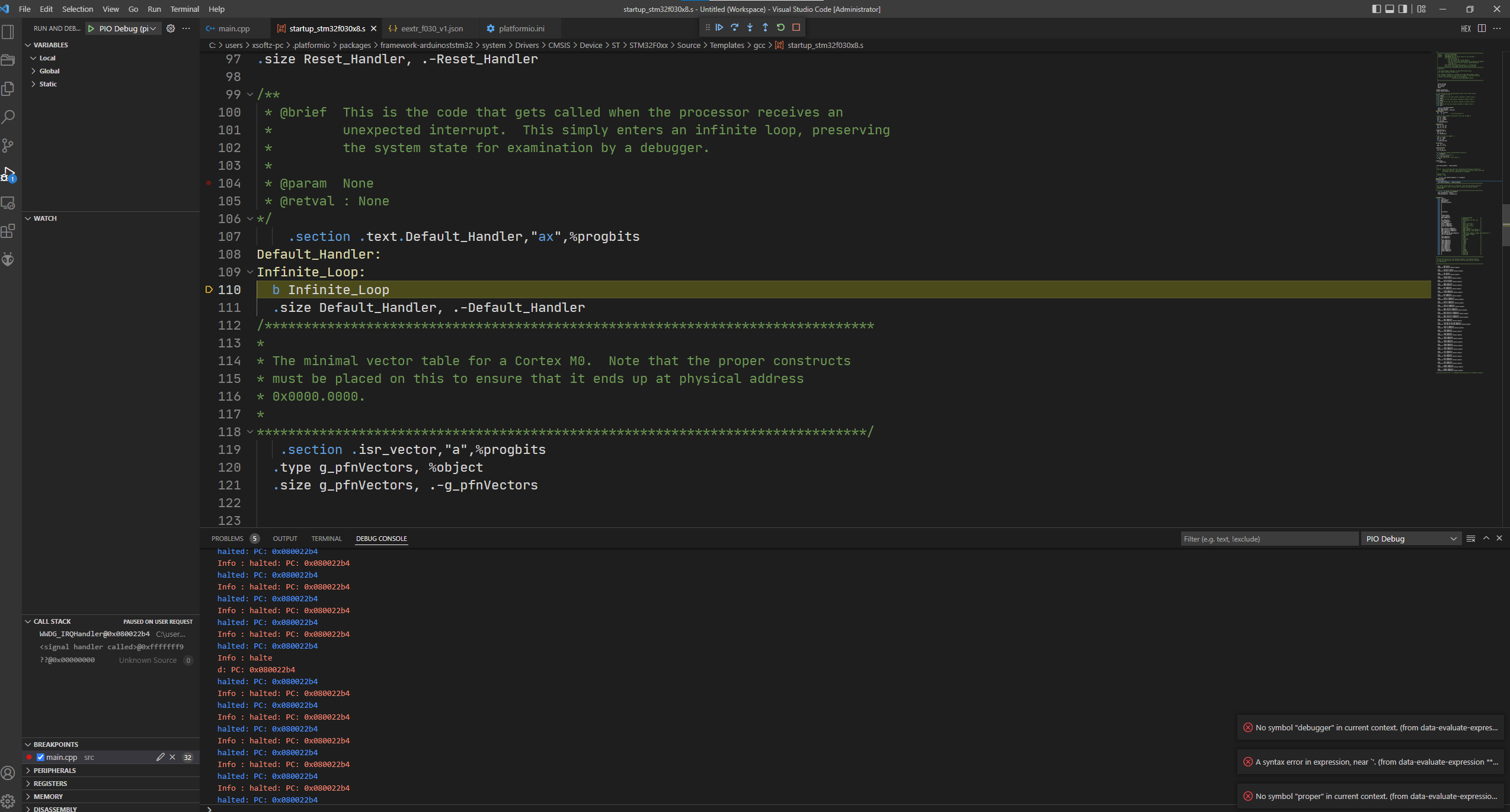
Press the “pause” button. Where is it stuck?
For the clock config you can copy-paste this piece of code at the bottom of the src/main.cpp
extern "C" void SystemClock_Config(void)
{
  RCC_ClkInitTypeDef RCC_ClkInitStruct;
  RCC_OscInitTypeDef RCC_OscInitStruct;

  /* No HSE Oscillator on Nucleo, Activate PLL with HSI/2 as source */
  RCC_OscInitStruct.OscillatorType = RCC_OSCILLATORTYPE_NONE;
  RCC_OscInitStruct.PLL.PLLState = RCC_PLL_ON;
  RCC_OscInitStruct.PLL.PLLSource = RCC_PLLSOURCE_HSI;
  RCC_OscInitStruct.PLL.PREDIV = RCC_PREDIV_DIV1;
  RCC_OscInitStruct.PLL.PLLMUL = RCC_PLL_MUL12;
  if (HAL_RCC_OscConfig(&RCC_OscInitStruct) != HAL_OK) {
    /* Initialization Error */
    while (1);
  }

  /* Select PLL as system clock source and configure the HCLK, PCLK1 clocks dividers */
  RCC_ClkInitStruct.ClockType = (RCC_CLOCKTYPE_SYSCLK | RCC_CLOCKTYPE_HCLK | RCC_CLOCKTYPE_PCLK1);
  RCC_ClkInitStruct.SYSCLKSource = RCC_SYSCLKSOURCE_PLLCLK;
  RCC_ClkInitStruct.AHBCLKDivider = RCC_SYSCLK_DIV1;
  RCC_ClkInitStruct.APB1CLKDivider = RCC_HCLK_DIV1;
  if (HAL_RCC_ClockConfig(&RCC_ClkInitStruct, FLASH_LATENCY_1) != HAL_OK) {
    /* Initialization Error */
    while (1);
  }
}
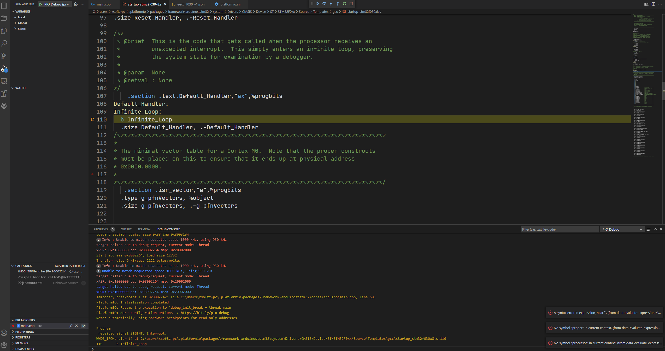
Hmm it’s stuck in the generic Default_Handler, which could be a hardfault, or anything really  .
.
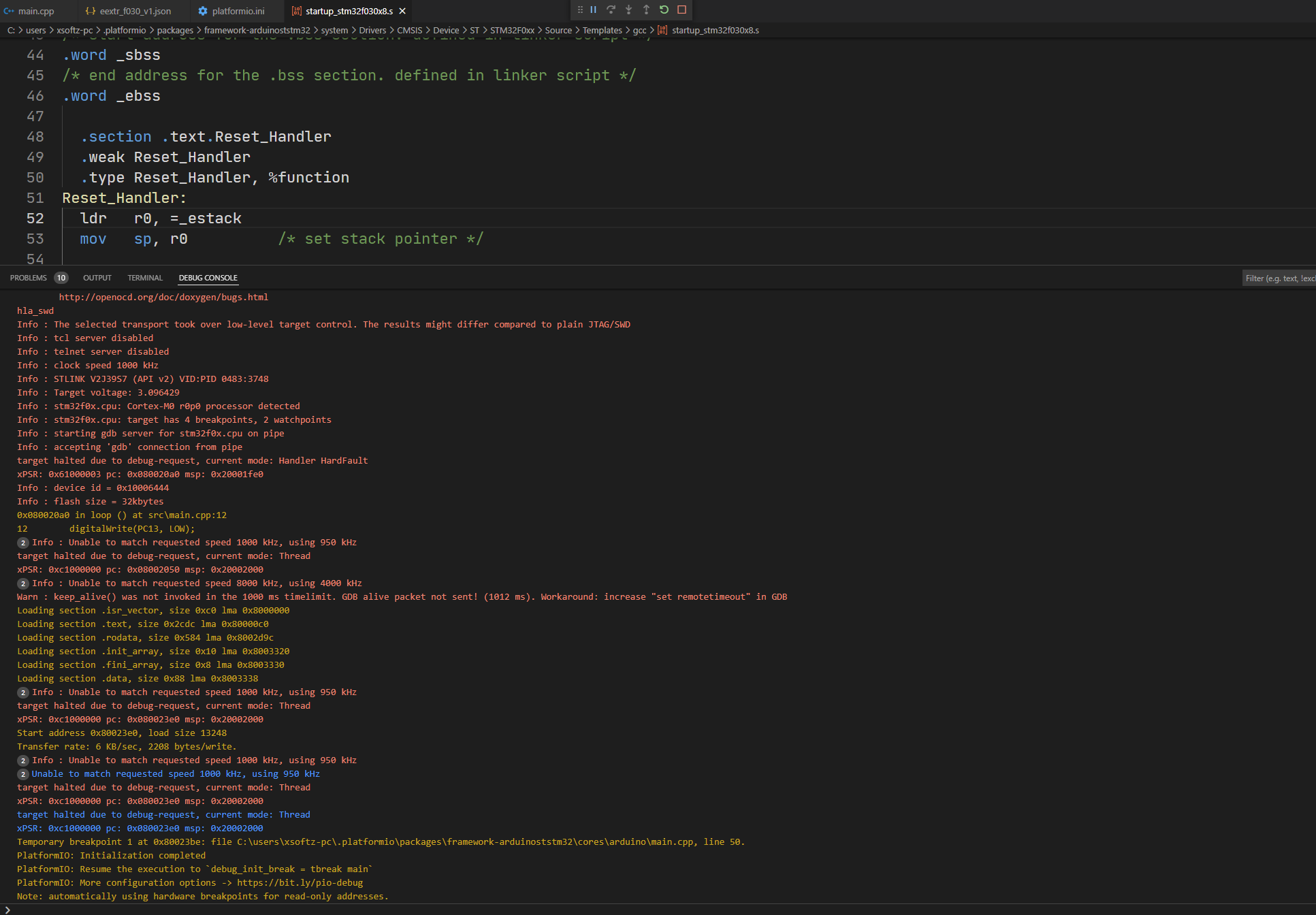
Can you please add
debug_init_break = break Reset_Handler
to the platformio.ini and stop debugging, then start debugging again? It should start at the Reset_Handler (first executed instruction) and you should be able to step through the (assembly) code line by line. At which line does it fail (by jumping to the Default_Handler)?
AH!! My bad! You don’t have a C8, but a C6!!
The C6 only has 4 KByte of RAM, the crash will come from that. (Setting SP into an area where there is no physical RAM will crash at the first push or branch).
I will need to create a new board file that uses F030C6T.
sorry for subject STM32F030C6T6
I have updated GitHub - maxgerhardt/pio-f030-test.
Please remove your old version + test latest version.
(EDIT: Had to reupload, now you can test.)
it work can runing !!
but not have list in platformio ?
if i make new project can use or how to make project ?
ldscript.ld << this can’t use ?
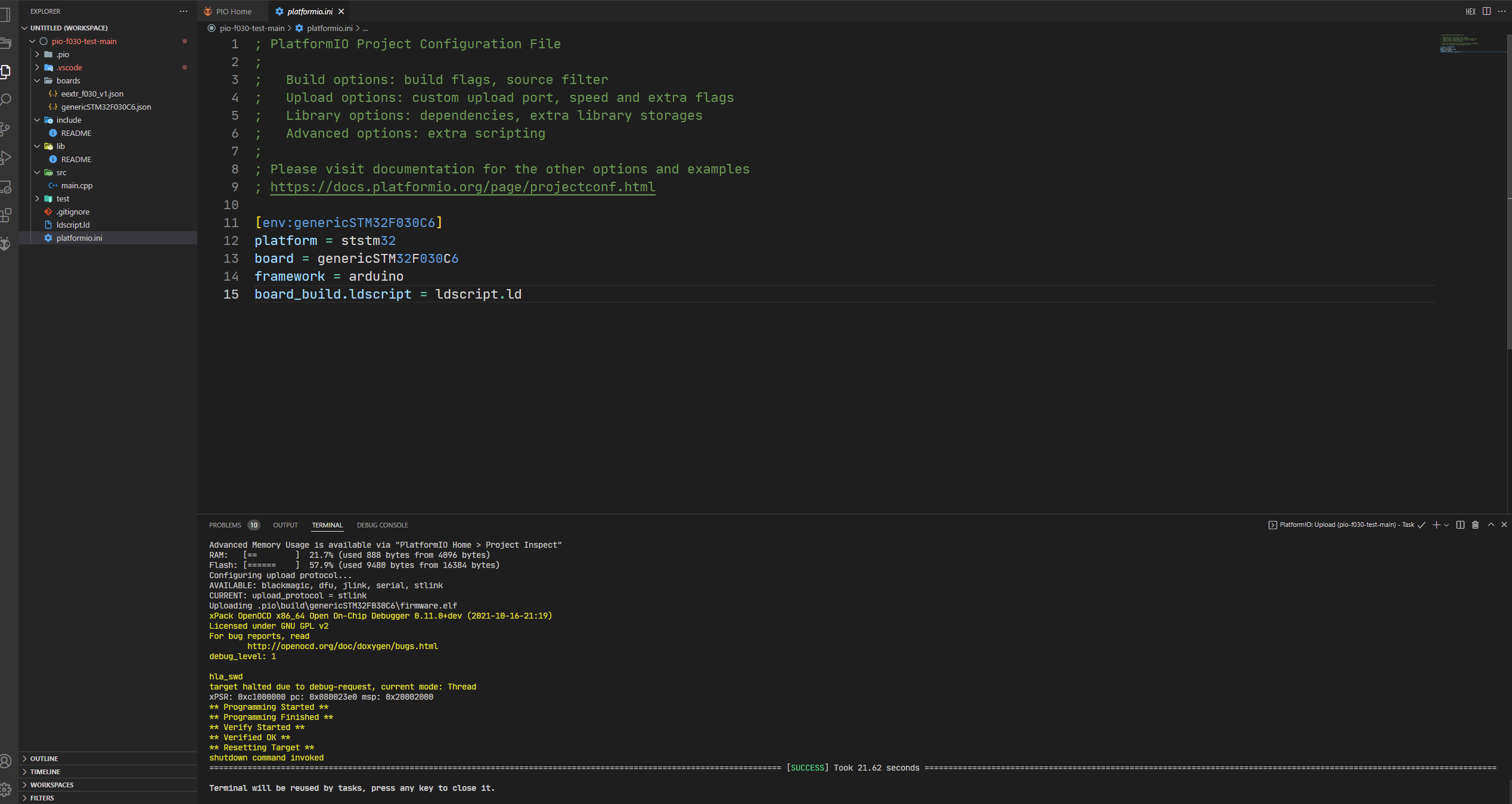
Yes, PlatformIO doesn’t have a genericSTM32F030C6 definition, or… any of the generic STM32F0 board definitions (JSON files). Only some “special” boards, like the Nucleo, or Disco(very) boards. This needs to be fixed by the developers.
What you need is the boards folder with the genericSTM32F030C6.json file (the other JSON file can be ignored), the ldscript.ld in the main project directoy and the platformio.ini with at least the current content.
The ldscript.ld you posted above is for a STM32F031 with all wrong flash + RAM sizes…
and doesn’t have the STM32Duino specific usages for LD_MAX_FLASH_SIZE etc. I copy-pasted the STM32F030 one since STM32Duino did not have one and compilation would fail and just changed comments, actual content stayed the same (since all things like Flash and RAM size is done via a variable set at link time).
I see you already opened How to use STM32F030C6T6 ? · Issue #623 · platformio/platform-ststm32 · GitHub. This is the correct way to go.
why i add
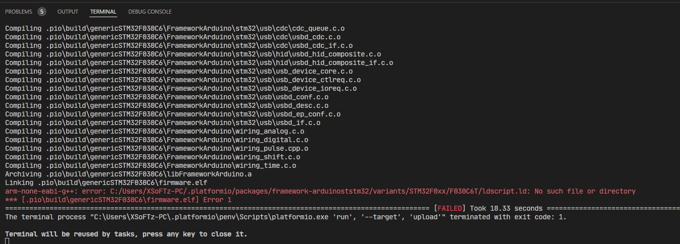
;board_build.ldscript = ldscript.ld
have
*** [.pio\build\genericSTM32F030C6\firmware.elf] Error 1
need use only all new project ?
If you comment it out, the builder script will try to find the linker script in the STM32Duino folder, but since Arduino_Core_STM32/variants/STM32F0xx/F030C6T at main · stm32duino/Arduino_Core_STM32 · GitHub does not have a ldscript.ld, it will fail.
That’s why you need the ldscript.ld file in the project folder and board_build.ldscript = ldscript.ld.
how to make file ldscript.ld for STM32F0xx ?
The linker script I posted is already valid, no need to make a new one.