The uploader only needs the COM port, not the Sipeed-Debug device (which is the RV-Link I guess?).
COM3 is an unrelated COM port?
It might be possible that something has gone wrong when connecting the debugger to the module, hard to say.
The way I see it in the schematics, debugging involves these sections
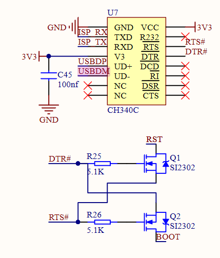

The USB-Serial converter is connected to the USB-C port on one side. The chip’s (UART) TXD signal is the K210’s ISP_RX signal and is directly connected to the chip. Conversely RXD is the K210’s ISP_TX. To make the K210 enter bootloader mode, the USB-Serial converter’s RTS and DTR pins are used as basically GPIO pins, controlling the RST and BOOT lines of the K210 through transistors (Q1 and Q2). This is basically the same concept as with the ESP32’s auto-reset circuit.
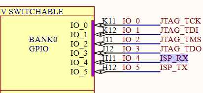
Using the pin diagrams as shown here you should be able to use a multimeter and check whether all signals are still connected properly, that is, check continuity between TXD (of the CH340C) and the pin after TDO (as marked in the linked pin diagram), then RXD, DTR to the transistor, RTS to the transistor, transistor to RST, transistor to BOOT, etc.
The ISP RX and TX lines are right after the JTAG connections. You might have disconnected something when soldering the JTAG signals in, or accidentally shorted a signal with another one.
Again, you might not need ISP (UART) programming if you can connect to the chip via JTAG. Have you tried starting debugging with the Sipeed RV Debugger?