First google result for multiple definition of '__vector_23':
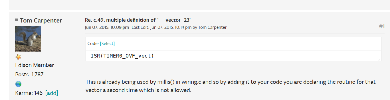
Looking at the code that doesn’t build, there is the ISR
This file is non-existant for your working 3.7.2 version, explaining why it works.
This issue with the new version is also already referenced in the project you linked to
With the solution
Which points to this Arduino core / board definition
Their core’s wiring.c has the “fix” which is surrounding the TIMER0 vector used by millis() with #ifdef 0. Read the comment for explanation.
So what you need to do is import the same core and variant definition as this project commands you to do. That is,
- go download https://github.com/3d-gussner/Arduino_Boards/tree/master/IDE_Board_Manager/prusa3drambo-1.0.1
- go to your
<home folder>/.platformio/packages/framework-arduinoavrfolder (<home folder>on Windows isC:\Users\<Username>\) - in
cores, add a new folderramboand copy-paste the contents of the core - in
variants, go to therambofolder and overwrite the.hfile with the one found here into the folder - add the following lines to the
platformio.inito adjust the used Arduino core
board_build.core = rambo
(board_build.variant must not be altered because it already is rambo)
(this is all documented in the documentation and board’s JSON file)