Yes, this is absolutely supported.
First it might help to get a better understanding of available ESP8266 modules and what makes them different from each other. See here and here.
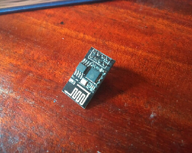
Then you’ll see that what you have is ESP-01 module. the very first and most basic / minimal type of ESP8266 module. All there is the ESP8266EX chip itself, the flash chip (on ESP-01 modules, this is usually 512KByte or 1MByte), a quartz crystal to drive it and the PCB antenna for WiFi.
It missing many convenience features of other modules and boards that make programming this chip easy. For example, the best way to get into ESP8266 development is to use a NodeMCU v2 board, in my opinion. It has a ESP-12F module, which is basically the ESP8266EX + 4MByte Flash + Crystal, and on-board a USB-serial converter which is connected to an auto-reset circuit, a 5V to 3.3V power supply (regulator), on board LEDs, antenna, and pin headers.
All of that except the bare chp is missing on your type of module and you will have to externally supply it.
That means the chip will need a 3.3V supply (with large decoupling capacitance, as during the WiFi startup, a lot of current will be drawn, which can make the supply voltage break down if not properly decoupled) and a 3.3V-level compatible UART dapter to program the chip (it’s programmed via a UART bootloader). Any external devices that you connect to the ESP8266 will need to either be 3.3V logic level. For 5V and other logic level devices, a level shifter must be used to not damage the ESP8266. Also, the chip needs a special reset sequence (GPIO0 to GND, then reset pulse) to enter bootloader mode for programming. This means that you must pull these bootloader pins to the right voltage somehow, e.g. by connecting them (RST + GPIO0) to two buttons to execute the reset sequence. Boards like the NodeMCU use a mechanism by which certain controllable GPIO lines of the USB-UART converter chip, and two transistors, are used to do the reset (A Beginner's Guide to the ESP8266).
There are dedicated ESP-01 programming adapters available that have the USB plug, USB-UART converter and power supply integrated. Some are better than others. E.g., the red ones are good because they have a slider that lets you control the GPIO0 pin to GND to enter bootloader mode easily. The ESP-01 and the adapter are commonly sold together. There’s another black one,but it doesn’t have a switch to control the bootloader mode.
As a beginner, the NodeMCU boards, or smaller Wemos D1 boards, are the best choice. But you can of course also make it work with the modules you have now and extra circuitry or adapters.
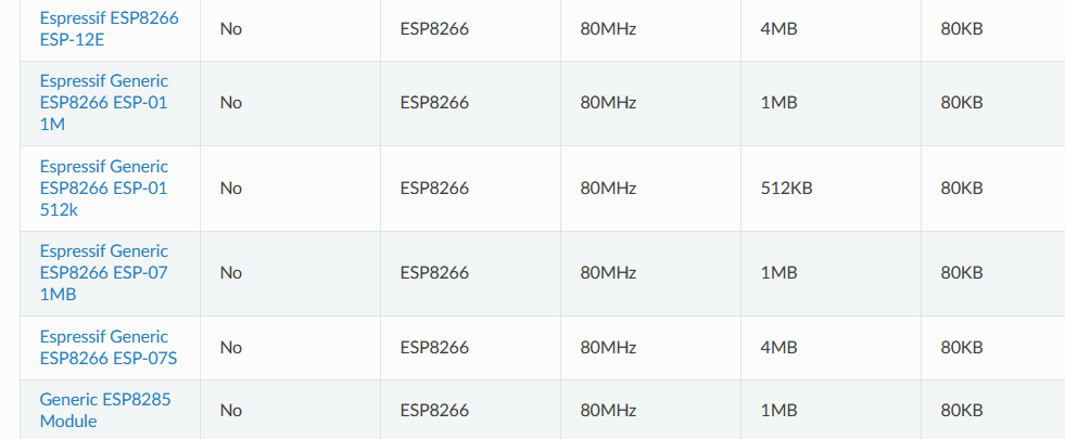
Here is also a tutorial on how to get the black adapter + ESP01 working in the normal Arduino IDE. Once you see it working there, it can be used normally in PIO with the e.g. ESP-01 1M configuration (assuming your module has a 1MByte flash, esptool.py will tell you that during flashing). Also see all possible configuration options for the ESP8266 that affect flashing.
I find that this tutorial shows a good breaboard setup with the ESP-01 if no adapter is used. Could maybe use a larger electrolytic capacitor for decoupling though.
It is also possible to use an Arduino Uno and 3 resistors (e.g. 10kOhm) for powering, programming and reading UART output of the ESP-01, see here.